(Translation provided by Sebastian Schmölling and Mamun Azmy)
Preparation
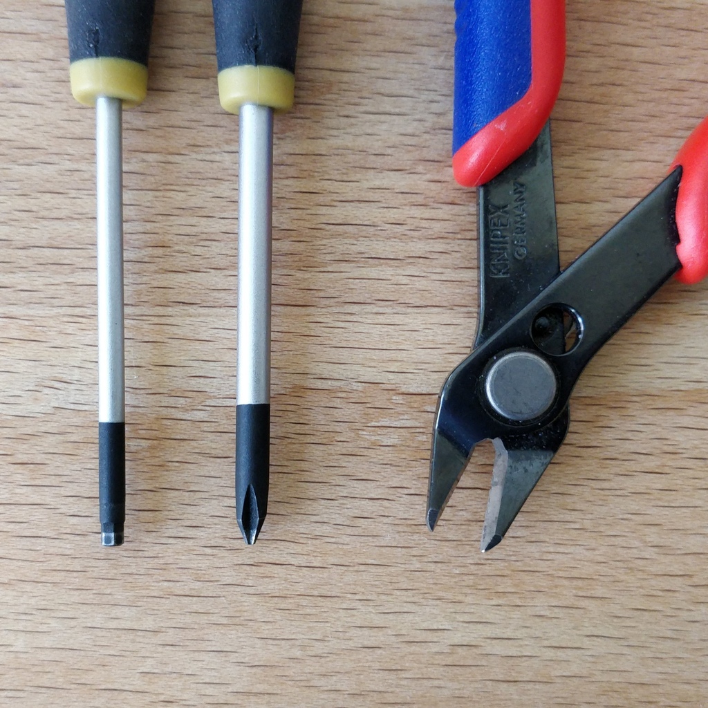
Tools
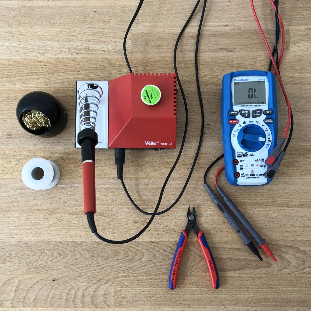
You will need the following tools to solder the Bakiwi electronics:
-
Soldering iron (or station) with a thin solder tip
-
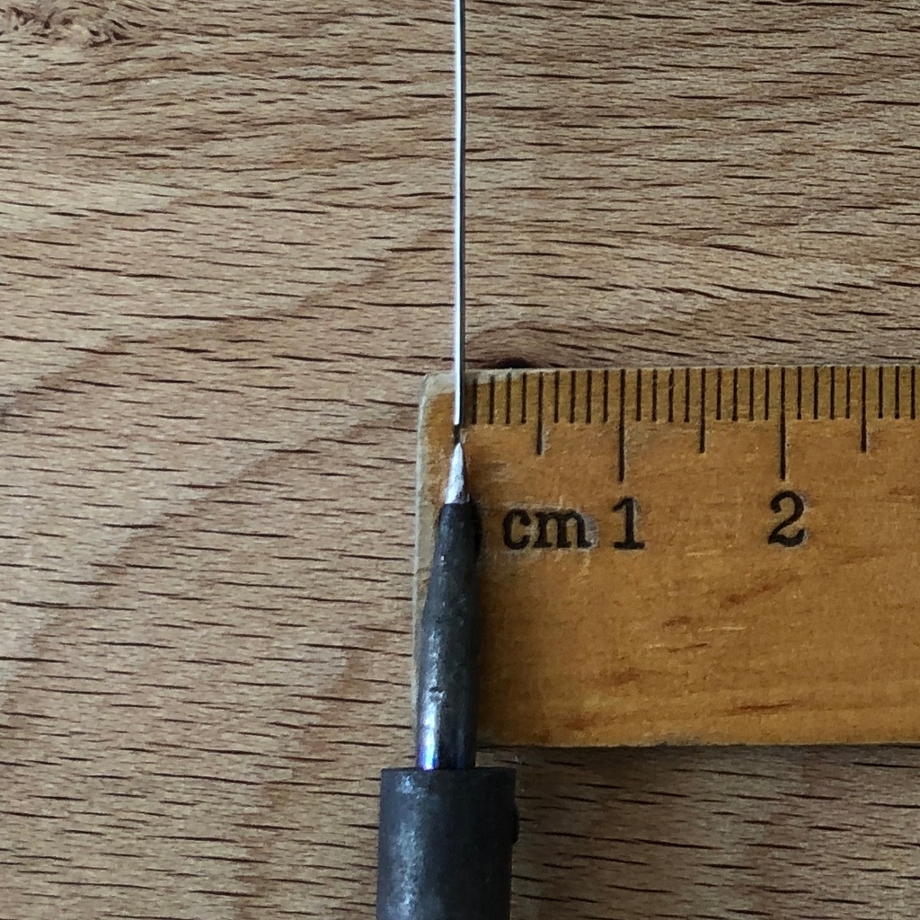
Tin solder (recommended: thickness 0.5-0.75mm with integrated flux, lead-free)
-
Brass wool with container ("dry cleaner"), alternatively a moistened sponge
-
Diagonal cutters or pliers
-
Multimeter (optional)
|
Note
|
If you have no soldering experience at all, we recommend that you watch an introductory video or tutorial beforehand in order to get a rough idea of soldering. It is even better if you assemble the kit with someone else who can already do a little bit of soldering. |
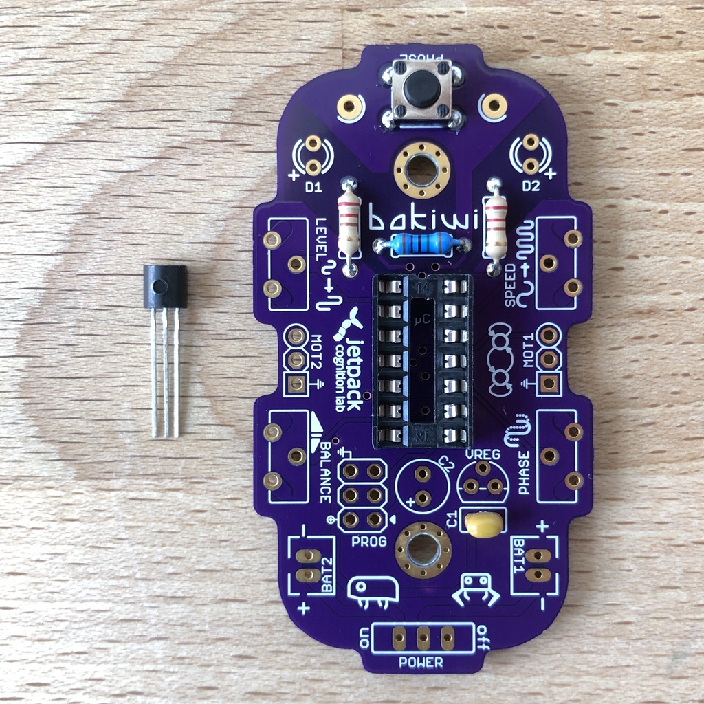
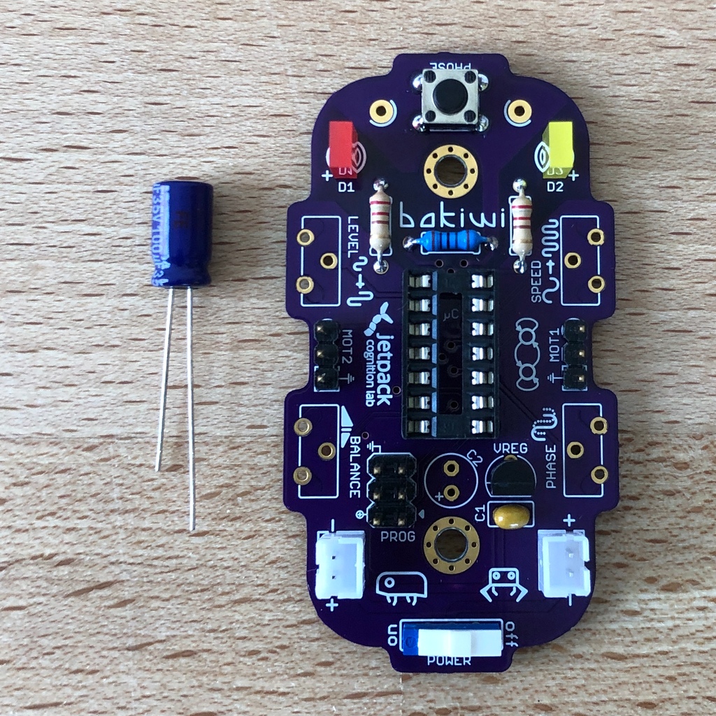
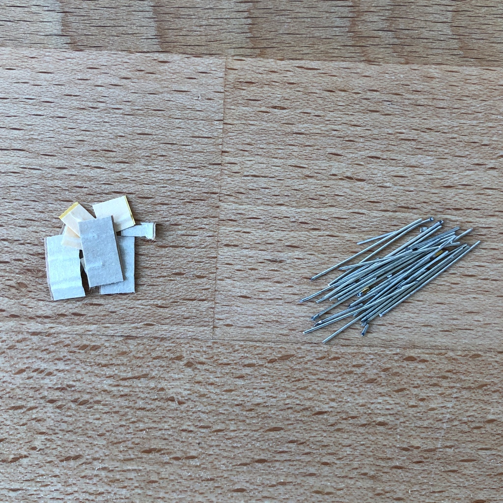
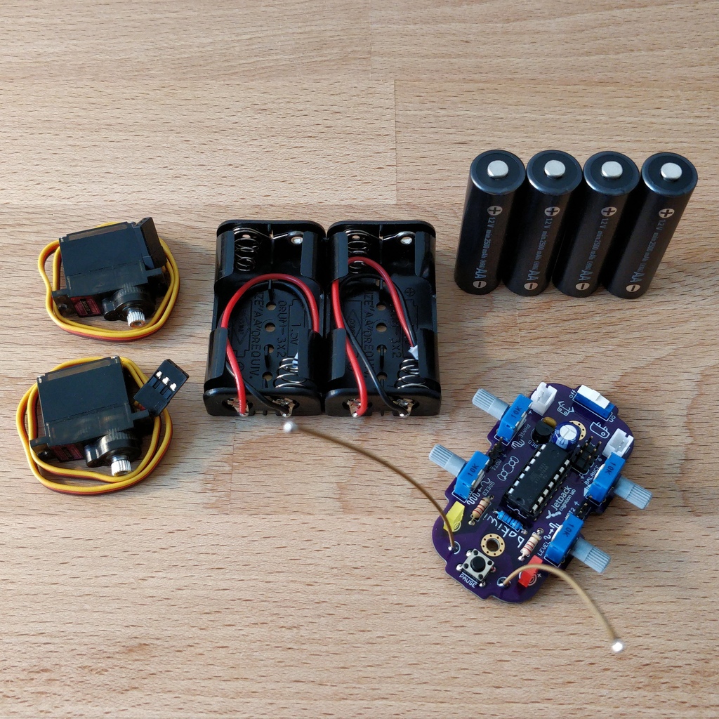
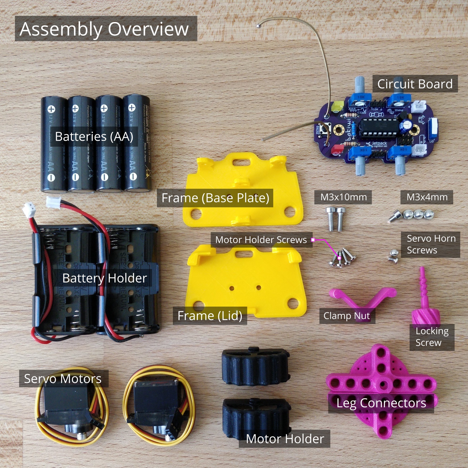
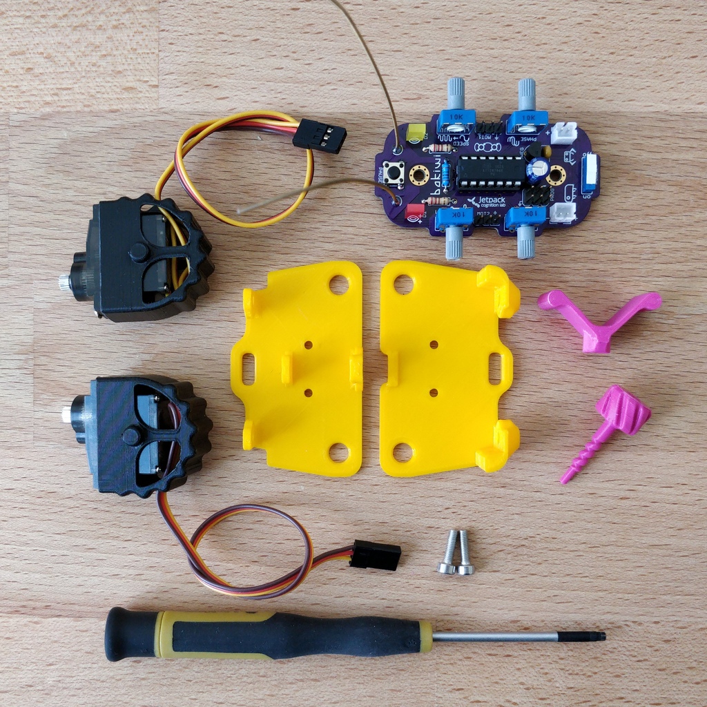
View components
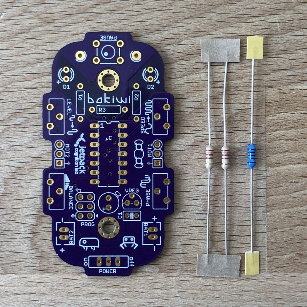
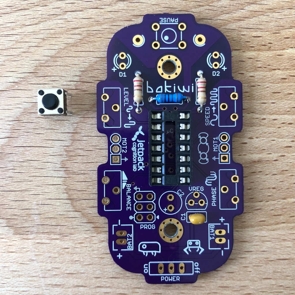
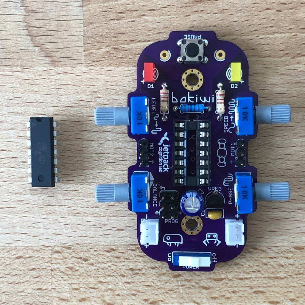
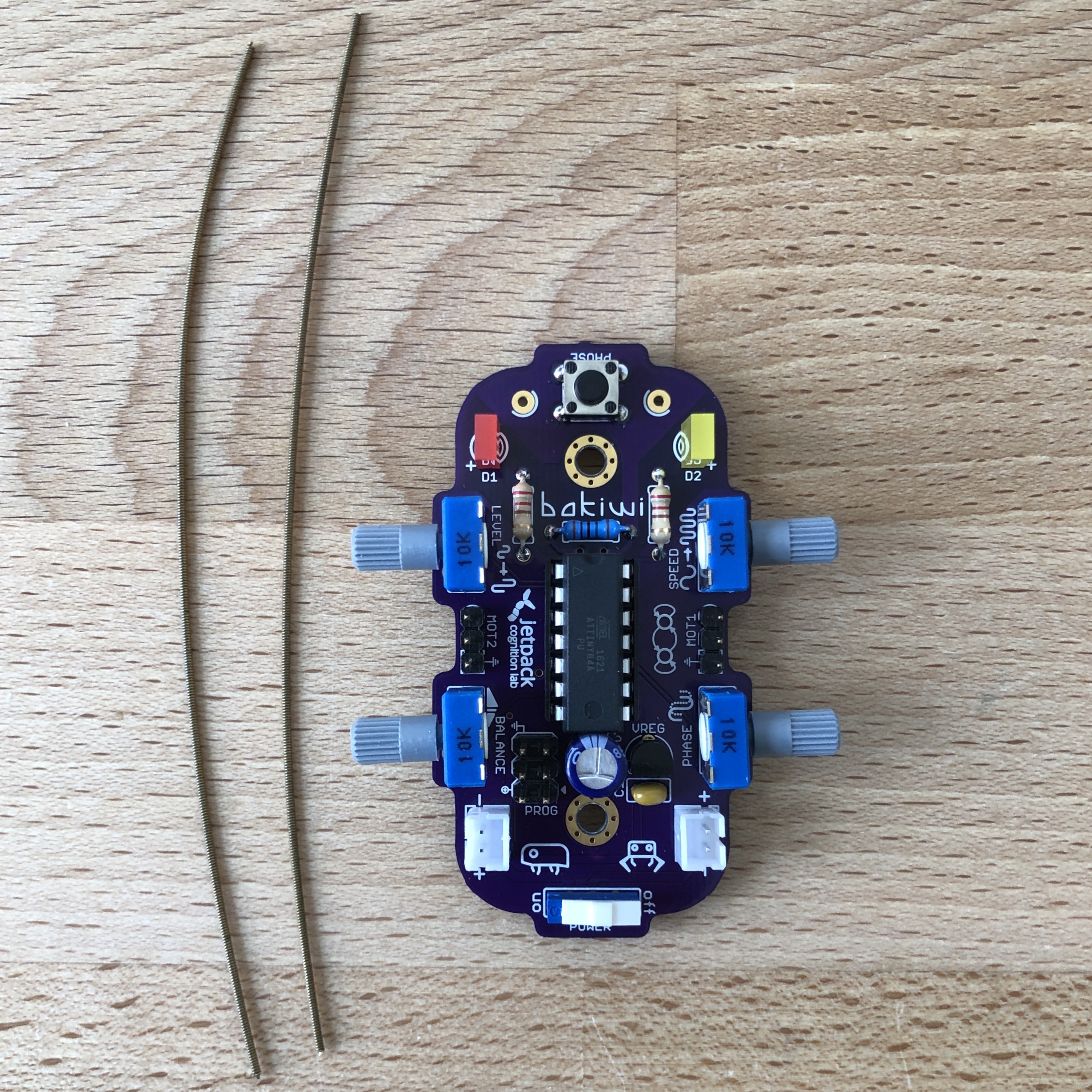
Check all components for completeness. In addition to the parts shown, you may have included material that is suitable for the antennae of your Bakiwi, e. g. pieces of guitar strings or pipe cleaners.
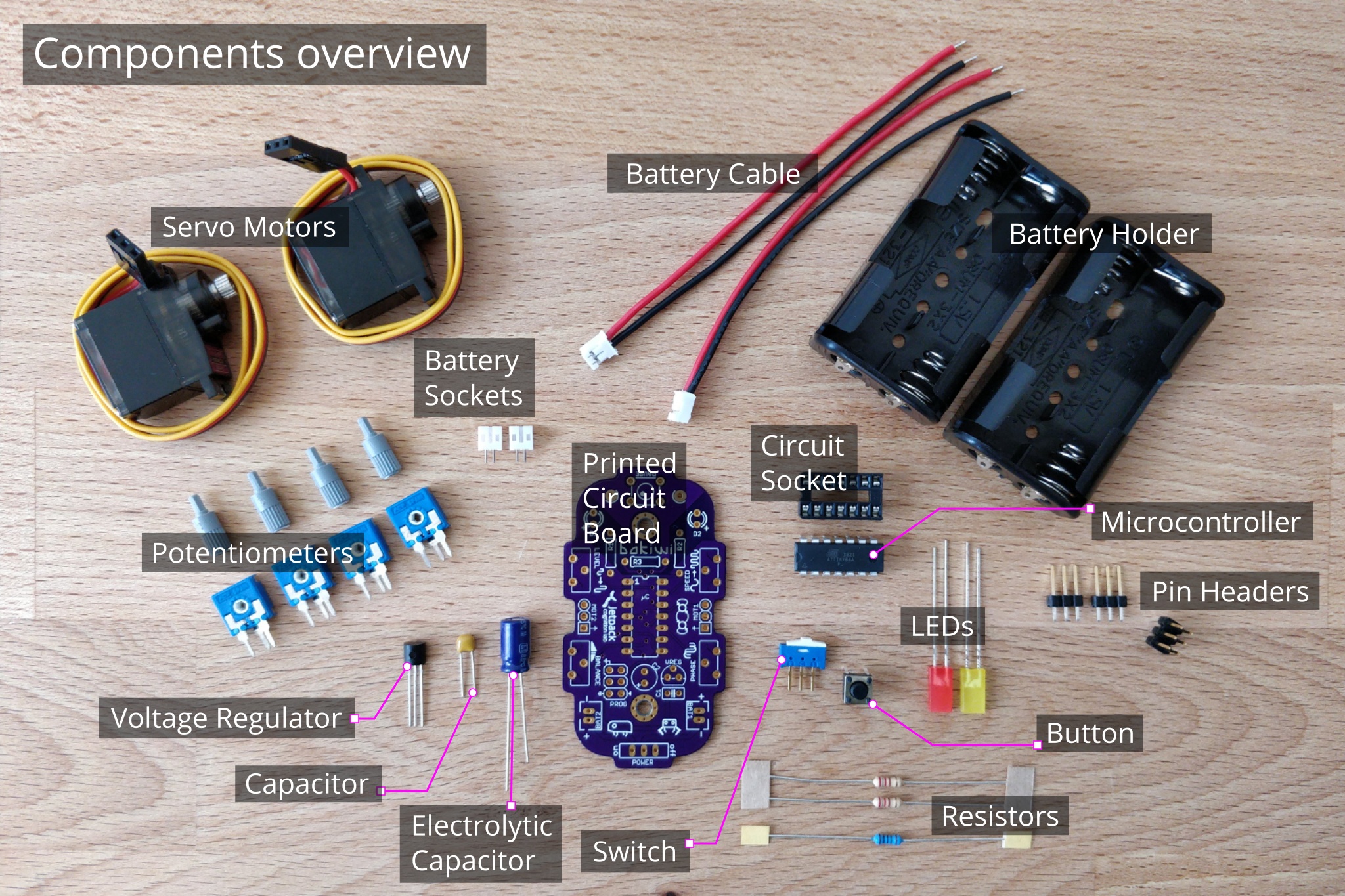
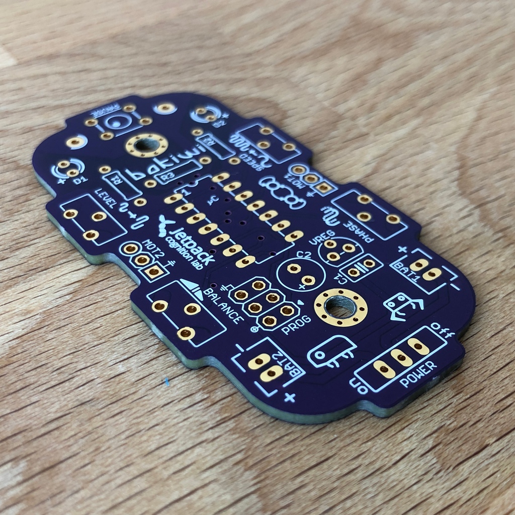
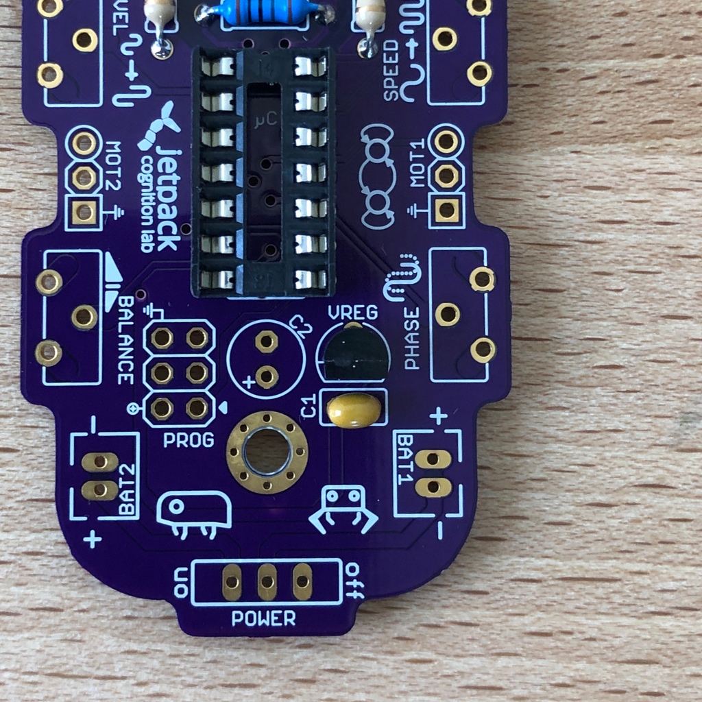
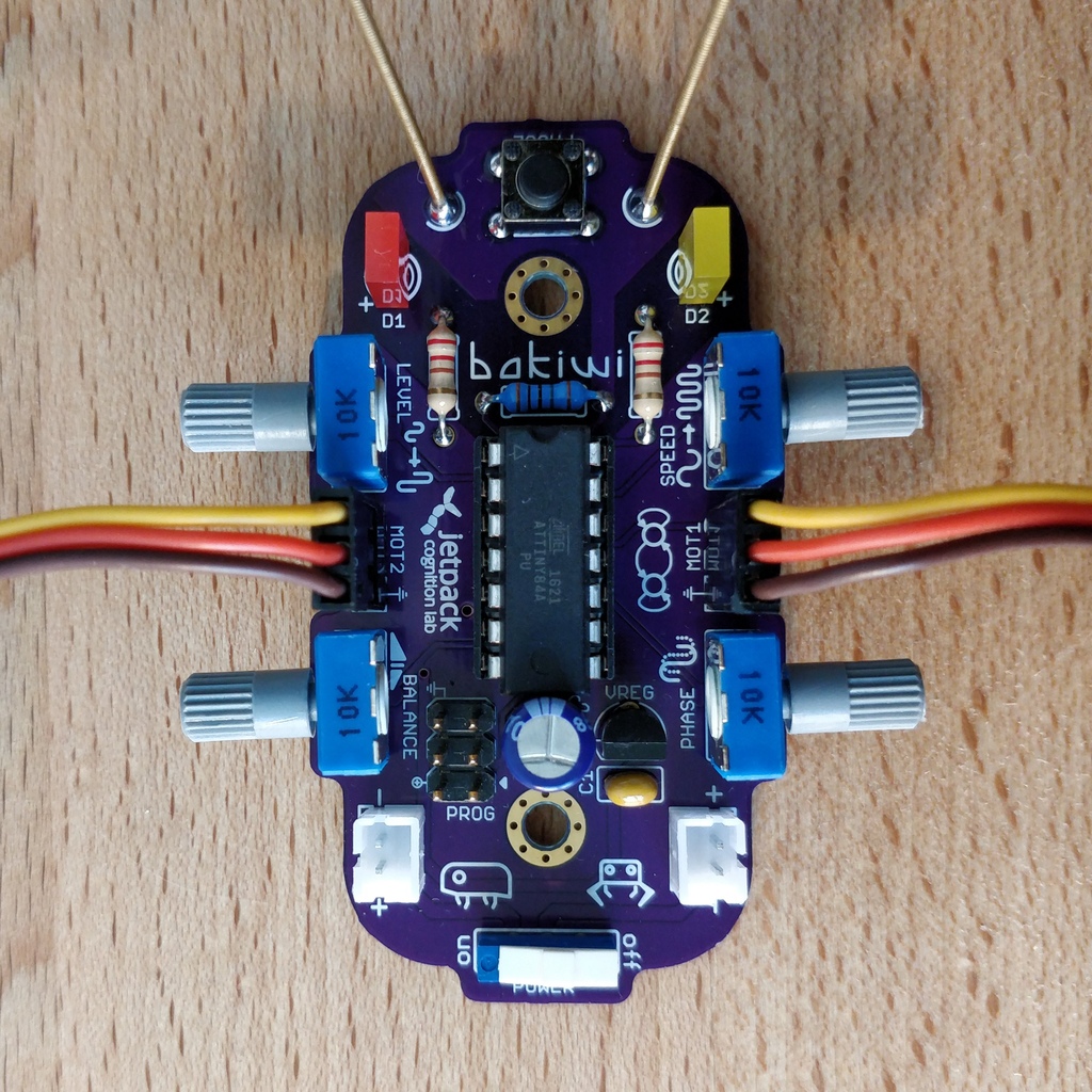
Put all the small parts in a container so that none can be lost. First, take the Bakiwi board and place it in front of you so you can read the Bakiwi label. The top of the board is the one with all the component labels. All components will now be inserted and soldered one by one in individually explained steps. Each component is inserted from the top and soldered on the bottom.
Turn on the soldering station and check the temperature display. If the temperature is adjustable, set it to match the recommended temperature of your solder (note the label). If you are unsure, start with 330°C, depending on the performance of the soldering station, a slightly higher temperature may be necessary. If the soldering feels sticky, then the temperature might be too low. If needed, gradually increase the temperature until the solder melts easily.
|
Tip
|
If your soldering tip no longer shines even with constant cleaning and keeps getting dark, the temperature is probably set too high. |
Take your time!
Soldering your Bakiwi requires calm and concentration. The time required varies from person to person and depends very much on previous knowledge. Absolute newbies should plan 2 hours for soldering, professionals can do it in 30 minutes.
1. Solder the components
1.1. Resistors
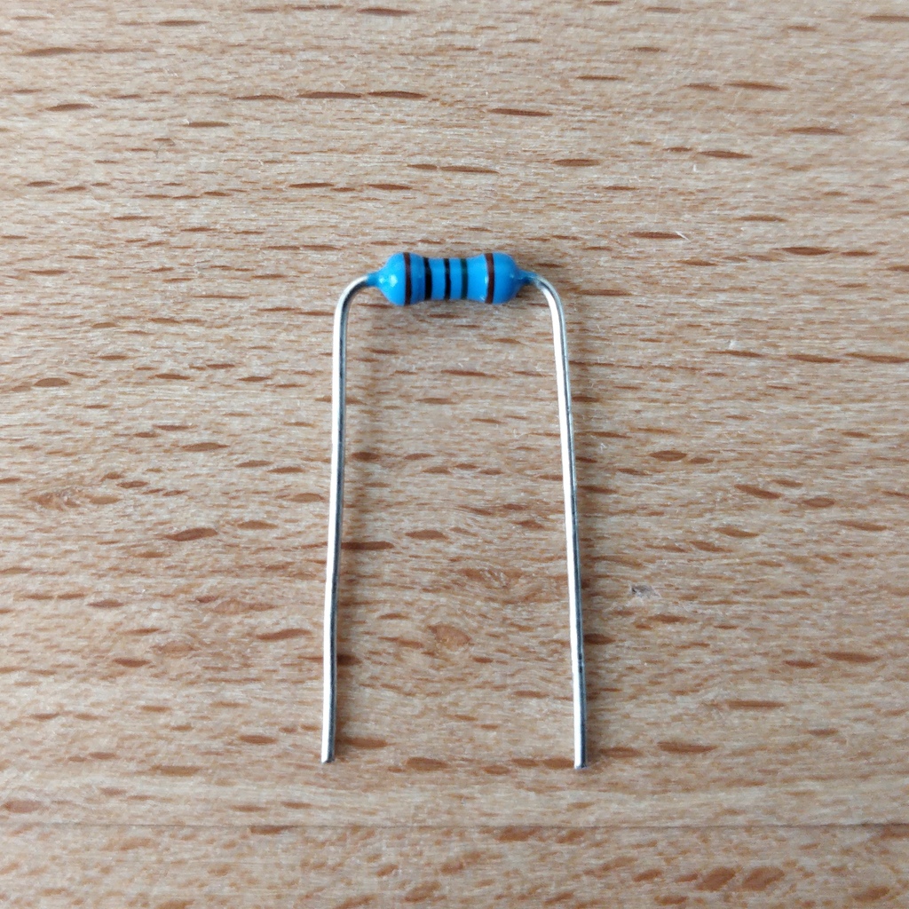
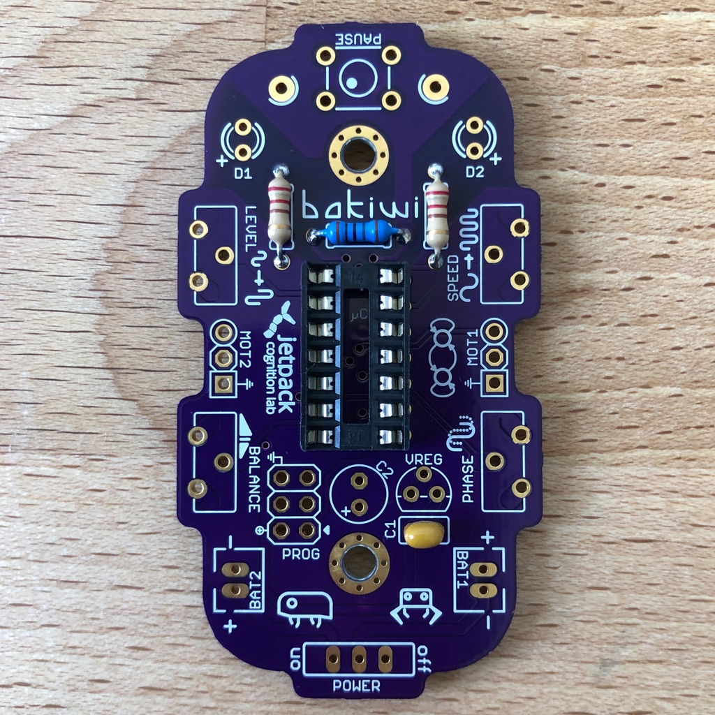
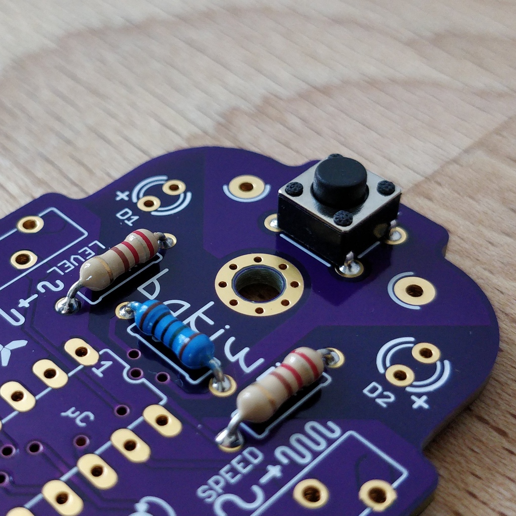
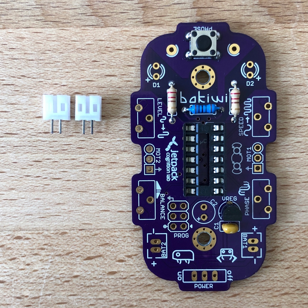
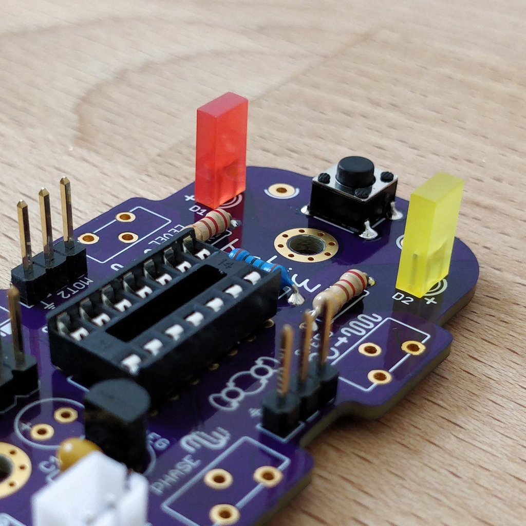
Look for the resistors. There is one blue and two beige ones. Start by peeling off the paper at either end of the blue resistor.

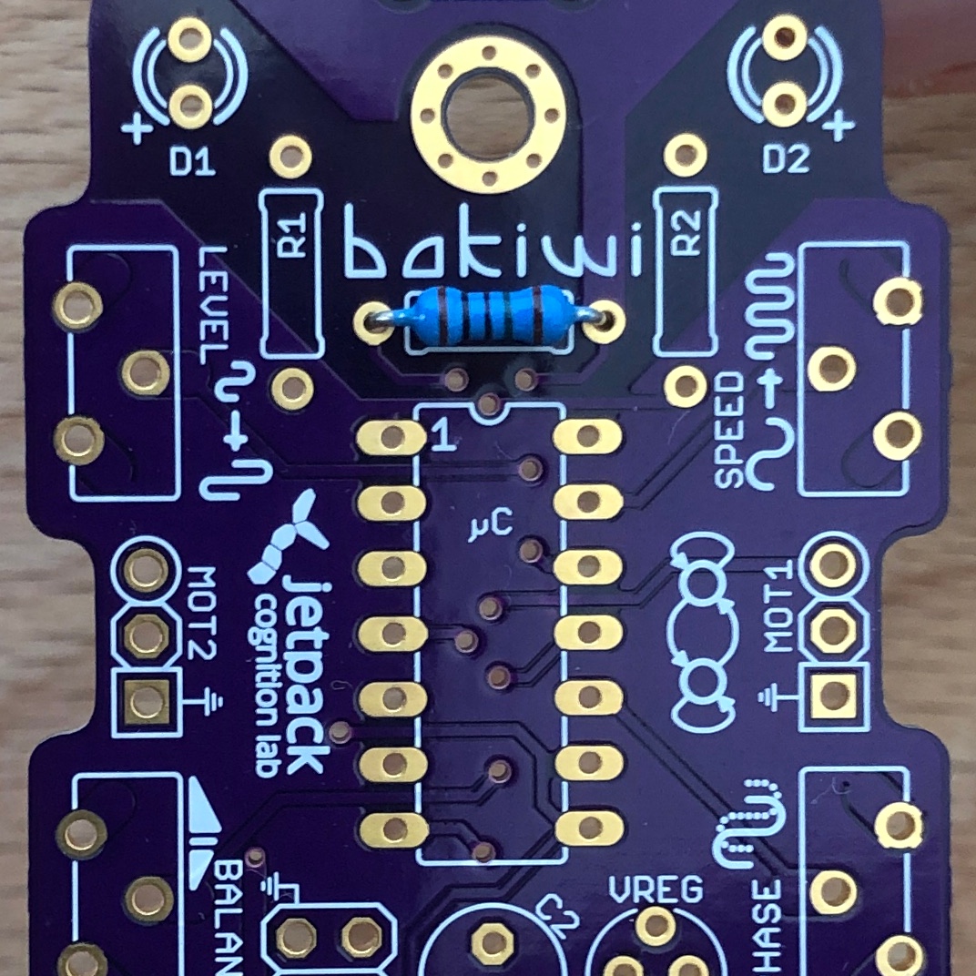
Now bend the two wire ends with your fingers directly at their origin so that they both point in the same direction and the two wires are parallel to each other. The blue resistor has the name R3. Look for the resistor symbol shown on the circuit board, it is located directly below the Bakiwi-label. Place it on the circuit board as shown in the picture. A resistor has no polarity, so it doesn’t matter which way you put it in.
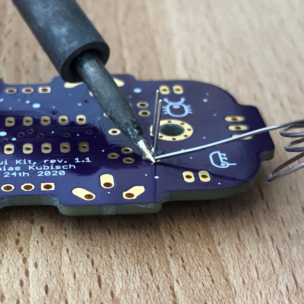
Hold the inserted component with your fingers, carefully flip over the circuit board and place it in front of you. Now start to solder the wire ends to the bottom side of the board. Make sure to touch and heat the wire and the soldering pad around the hole at the same time as you add the solder. The heat transfer works best when the soldering tip is clean and slightly coated with tin.
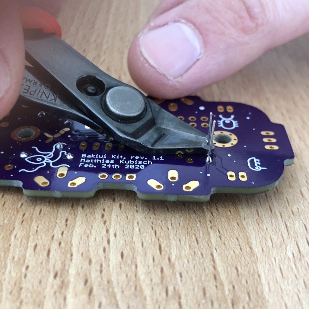
After that remove the wire ends by snapping them off with suitable pliers (e.g. wire cutters). Remove the wire as close as possible to your solder joint without damaging it.
Now take the other two resistors, R1 and R2 (beige). They are attached on either side of the Bakiwi-label. The order does not matter, you can also install both together. The steps are the same as for the first resistor.
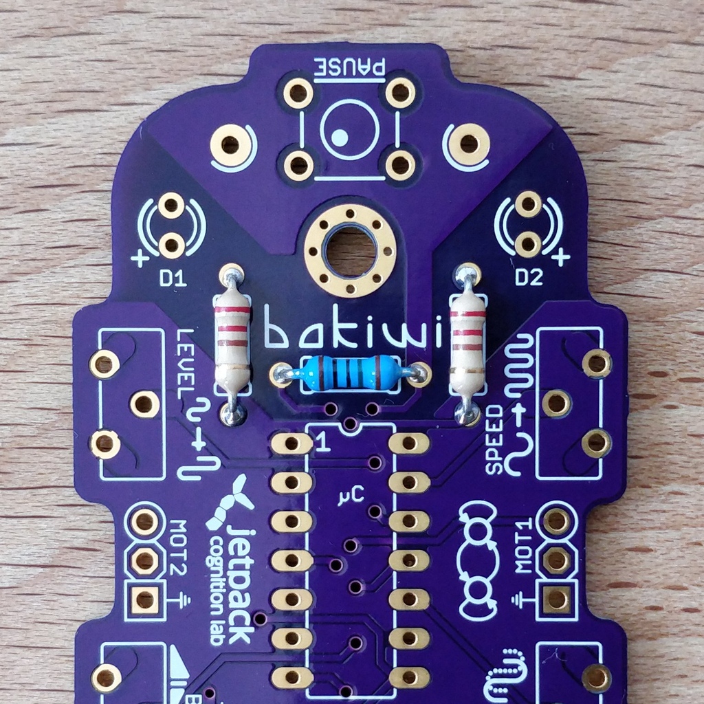
Congratulations. You have taken the first step. Compare your result with the picture.
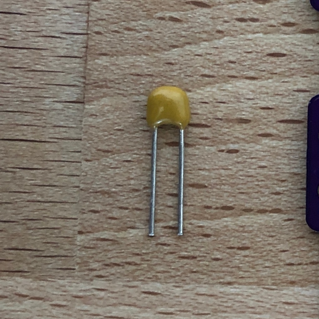
1.2. Capacitor
Now it’s the capacitor’s turn. Look for the small orange lense shaped component. Take the circuit board and look for the C1-marking.
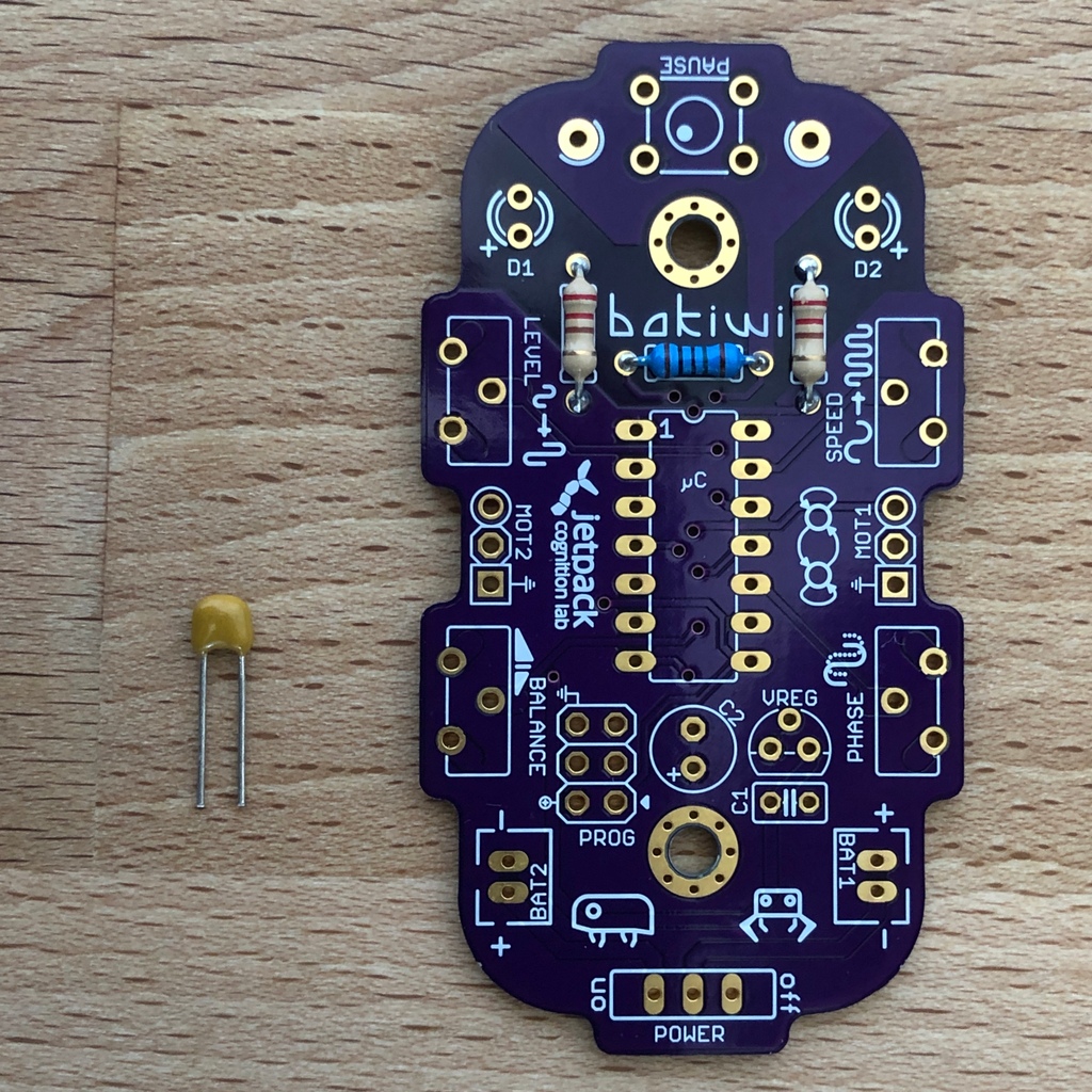

As with the resistors, the capacitor is plugged into the board from above and soldered on from below.
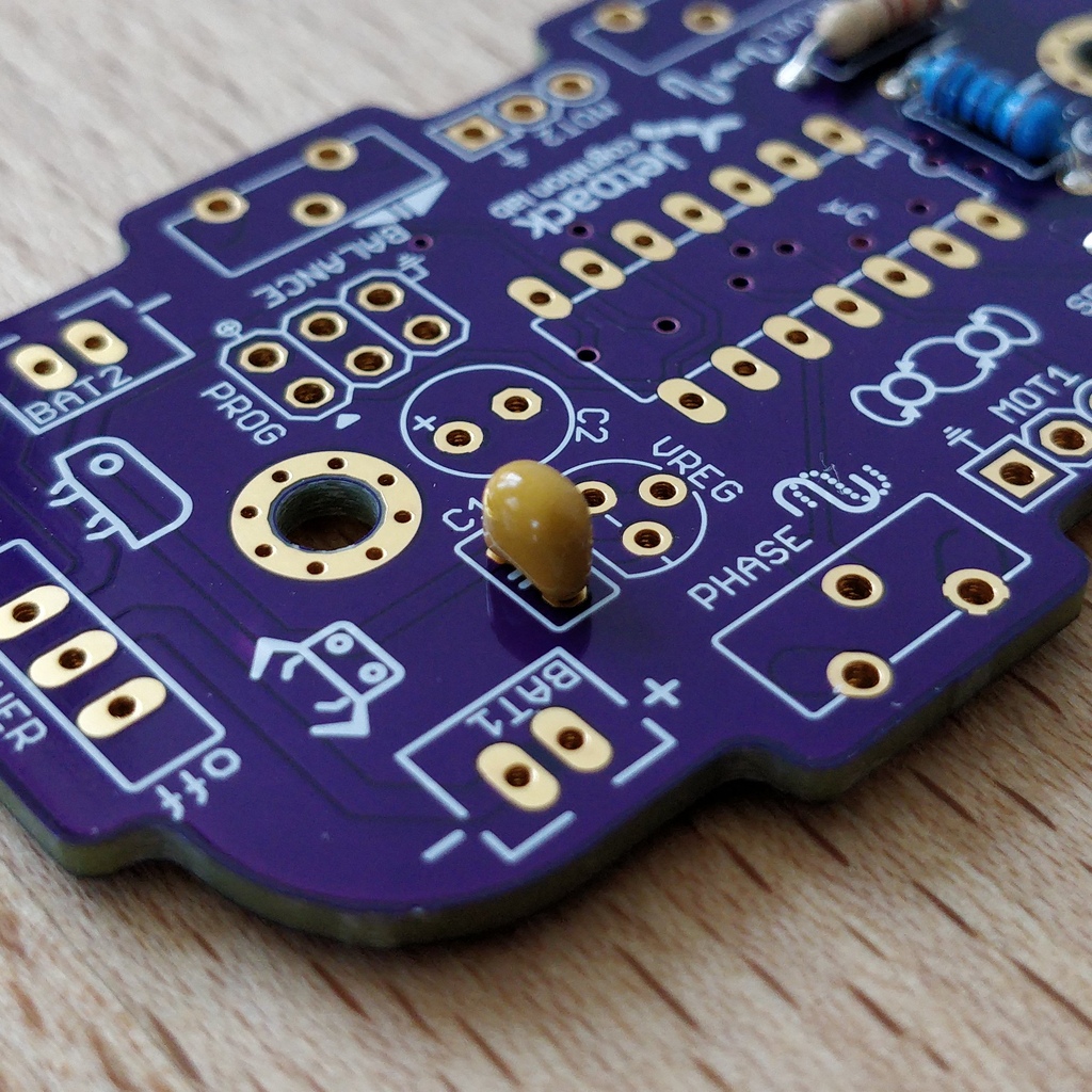
After soldering, cut off the wire ends again.
Done! This was the the warm-up. The next part is a little trickier.
1.3. Circuit Socket
The circuit socket has a total of 14 contact pins. That means you can now practice your soldering skills properly because all 14 solder joints are identical.
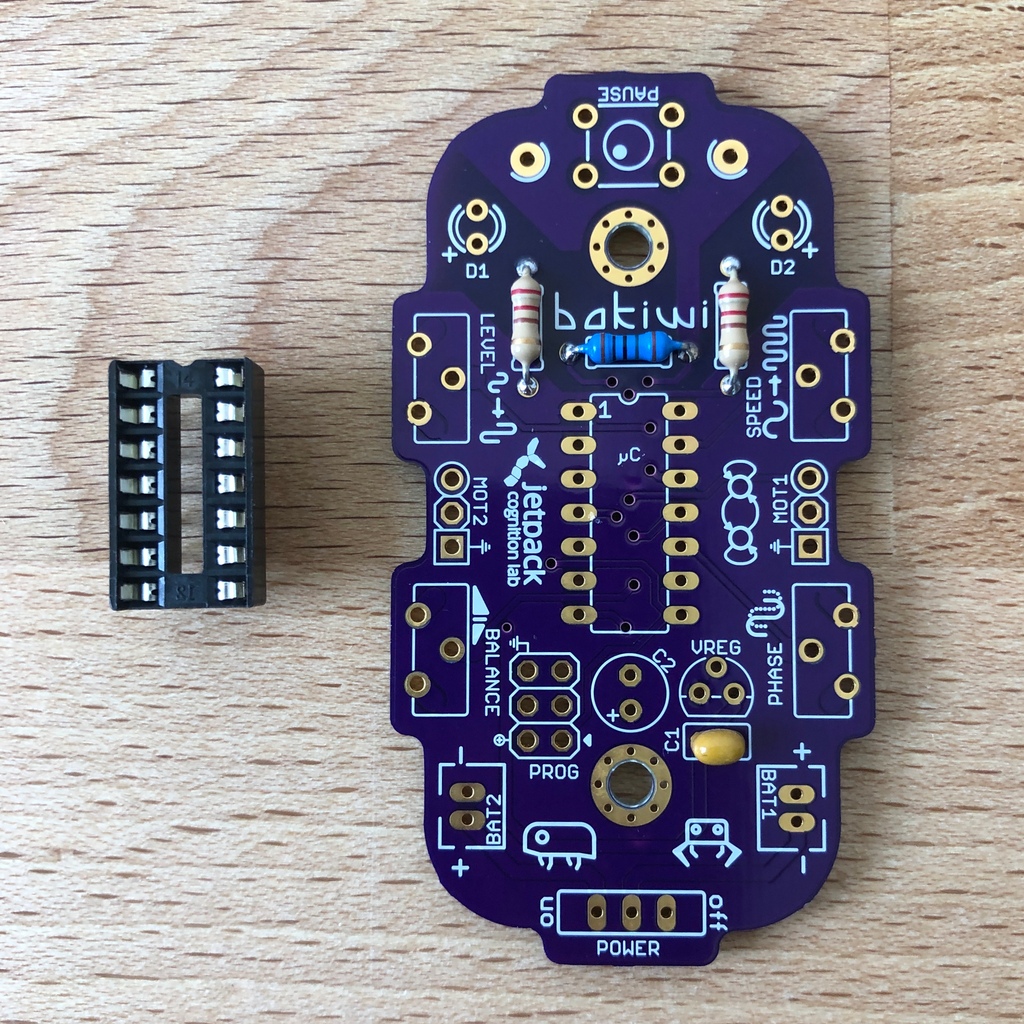
You can’t miss the position of the socket on the circuit board but there is a small notch on the socket that needs to be regarded. Make sure you put in the socket with the small notch facing the Bakiwi-logo as marked on the circuit board.
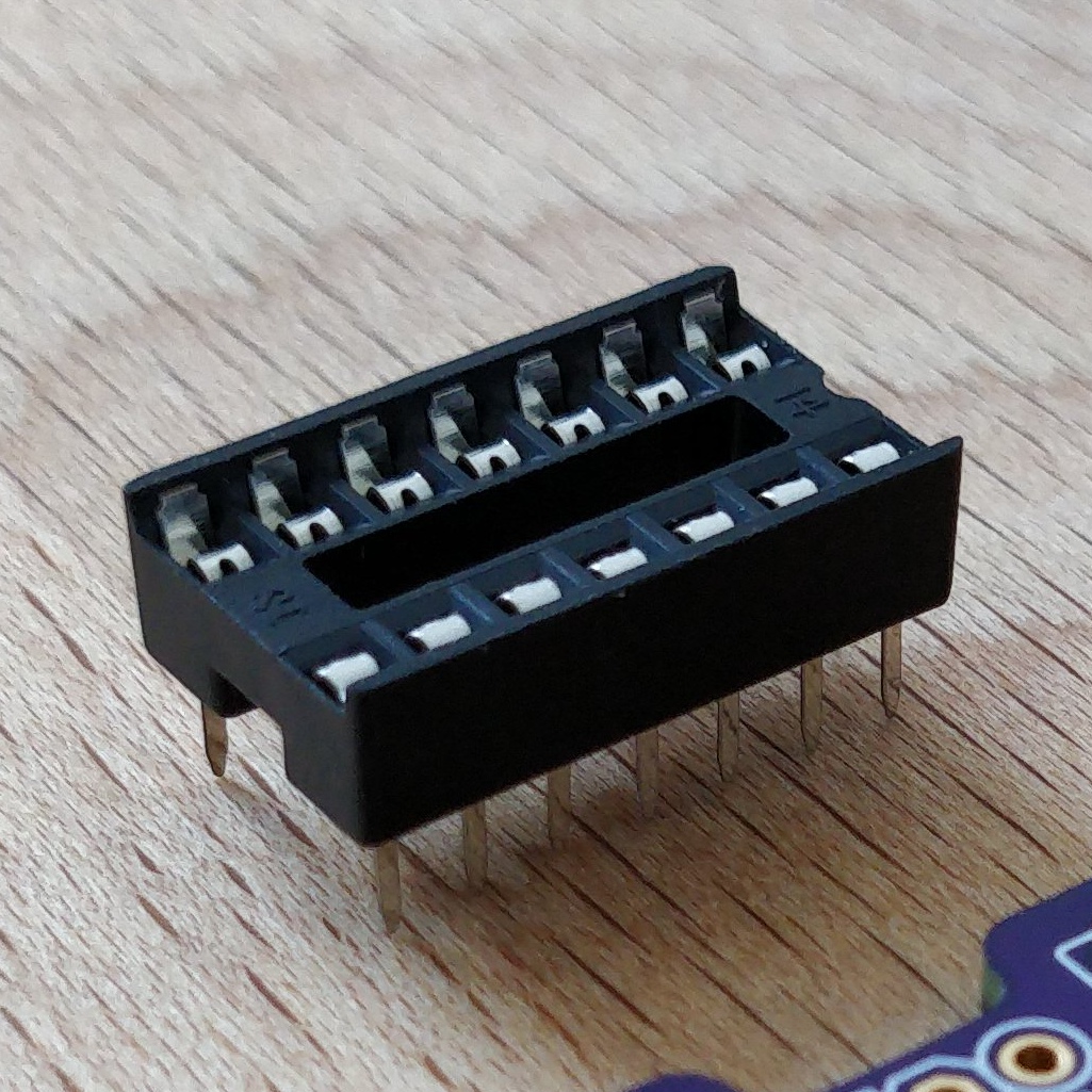
When soldering, make sure that you first solder on one corner and then the diagonally opposite corner. This way you can still tare the circuit socket a little, if needed.
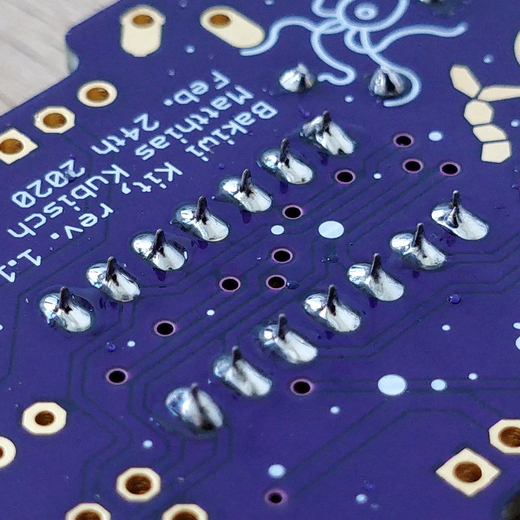
Tada. You have now already placed 22 solder joints on the Bakiwi board. If you haven’t soldered so much before, then you surely have the hang of it now.
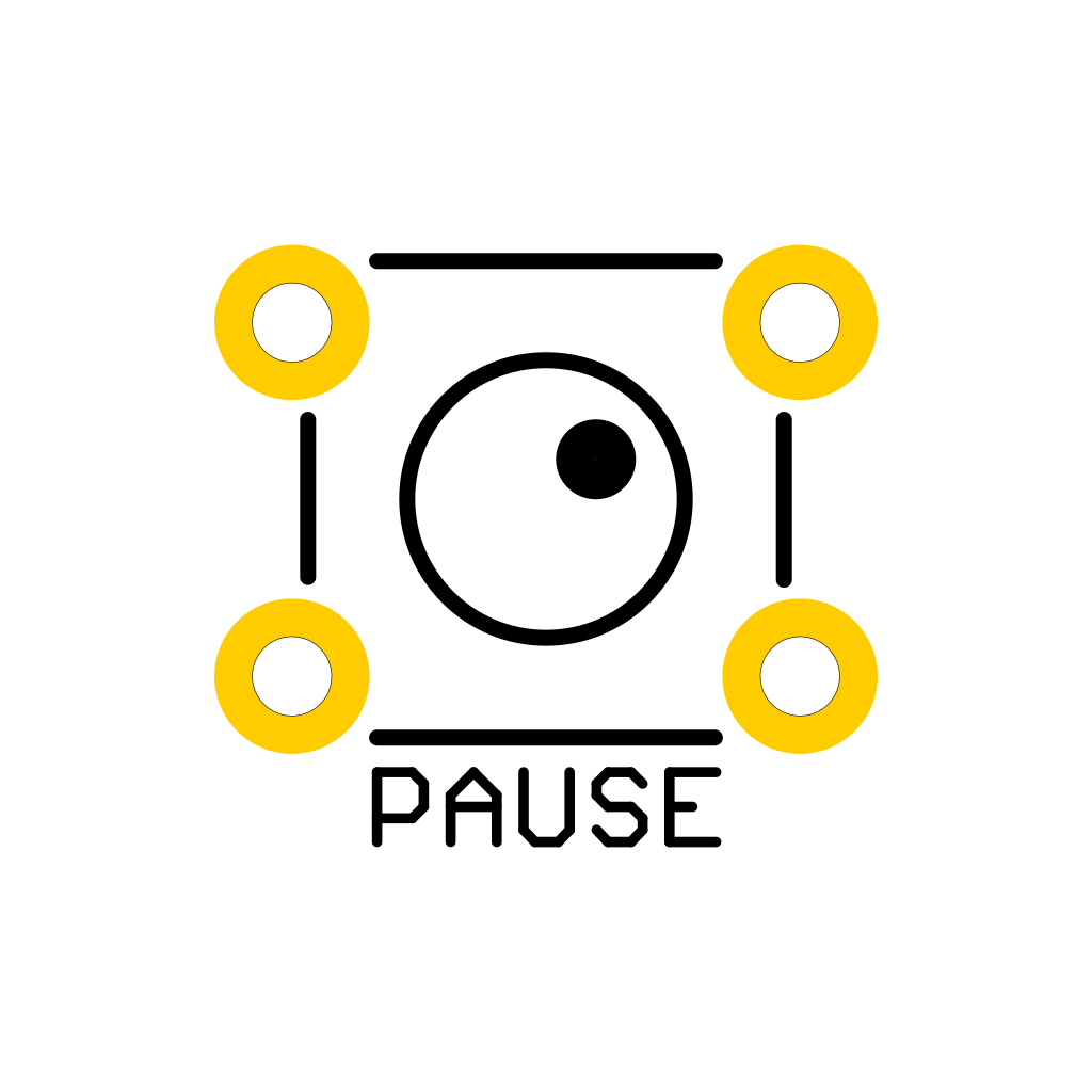
1.4. Button
Now look for the PAUSE marking on the circuit board and put in the button. If you can insert it with ease without bending the pins, it is automatically the right way round. You might hear a slight click when the button snaps in.
|
Important
|
The soldering pins of the button are a bit pointed, watch out for your fingers when inserting the button. After soldering in, you should remove these tips with pliers. |
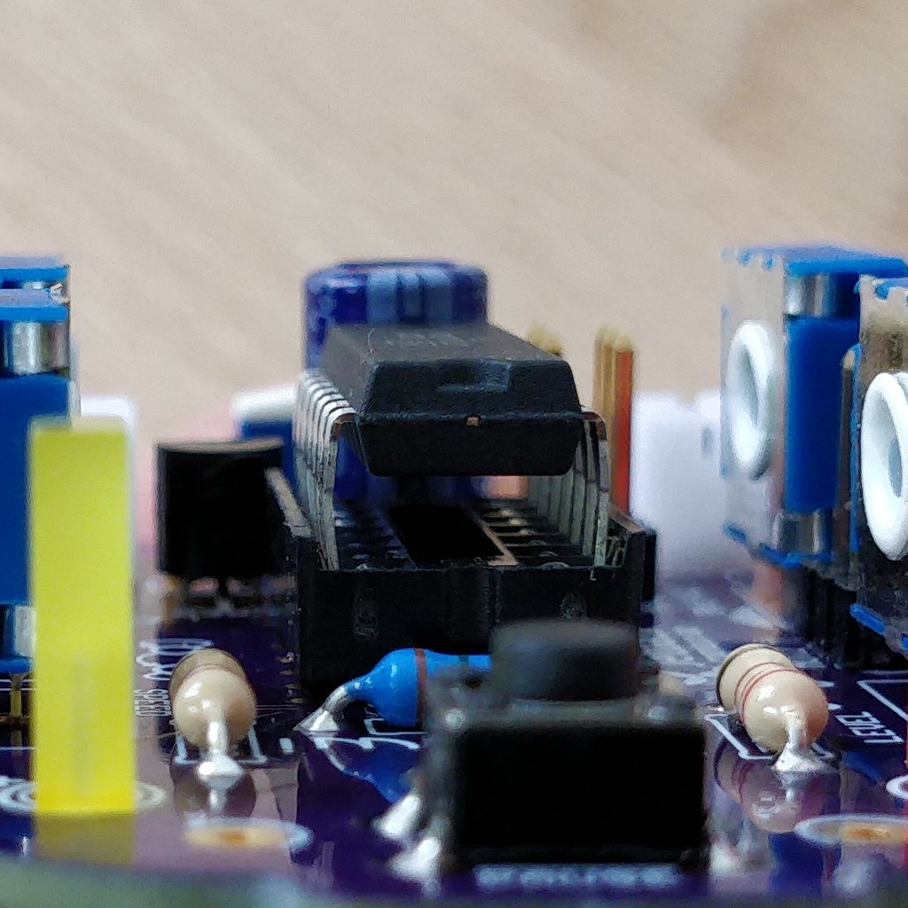
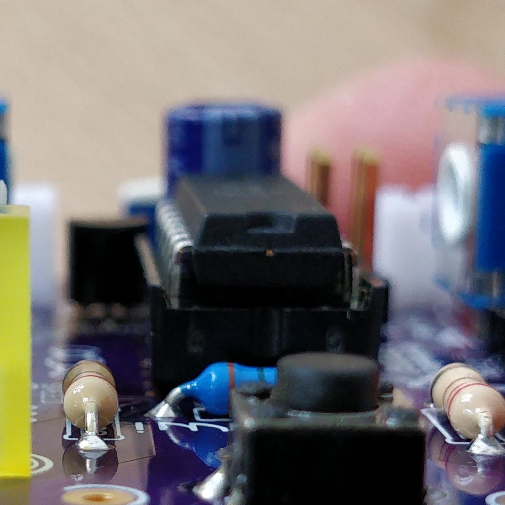
1.5. Voltage Regulator
The next component will be a little more difficult. Look for the VREG symbol on the circuit board. It can be found just above the orange capacitor and looks like a cut circle.

Attention! Now it’s getting a bit fiddly. The voltage regulator has three thin pins. The middle pin has to be bent so it fits onto the circuit board. You can use tweezers or a pencil, or try gently with your fingernail.
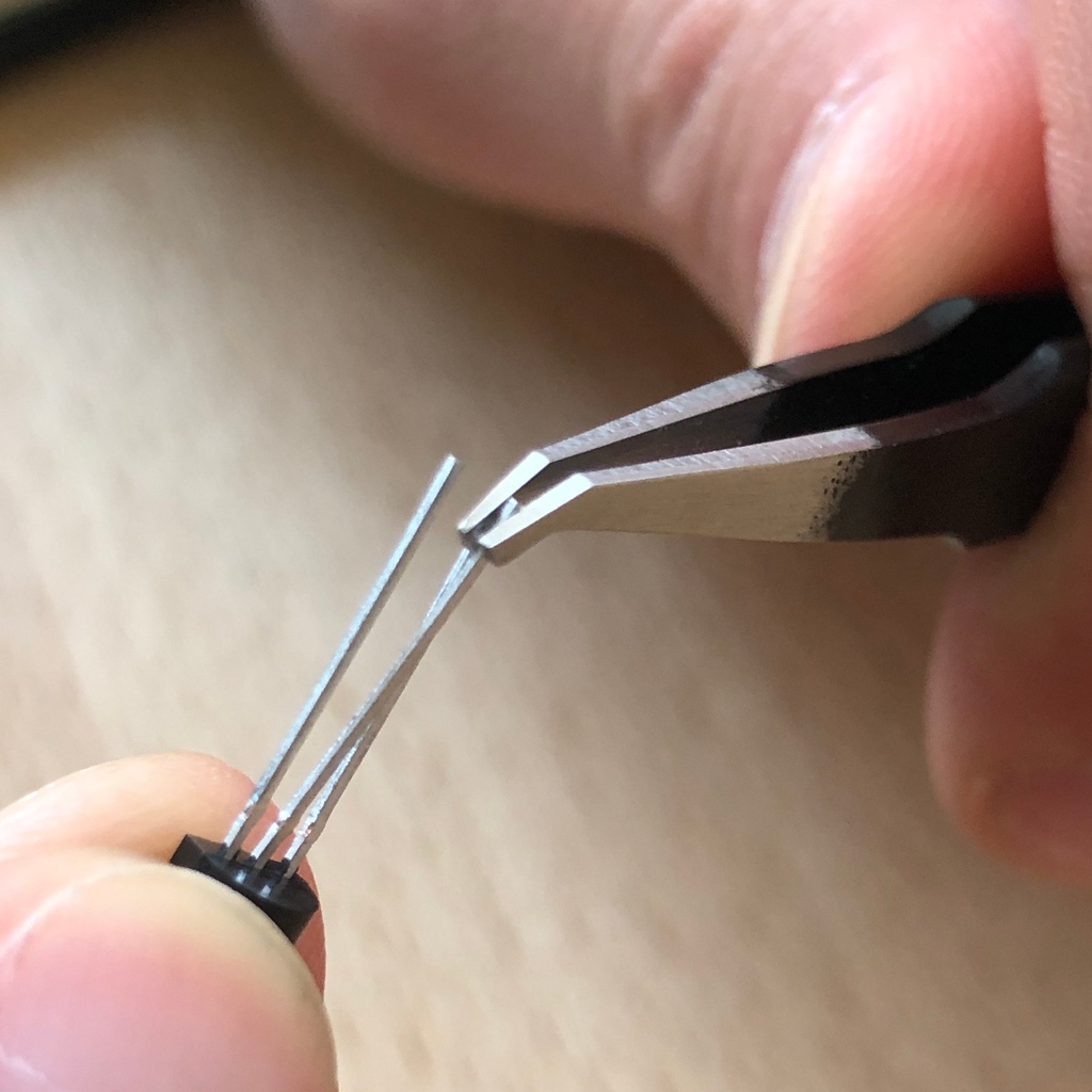
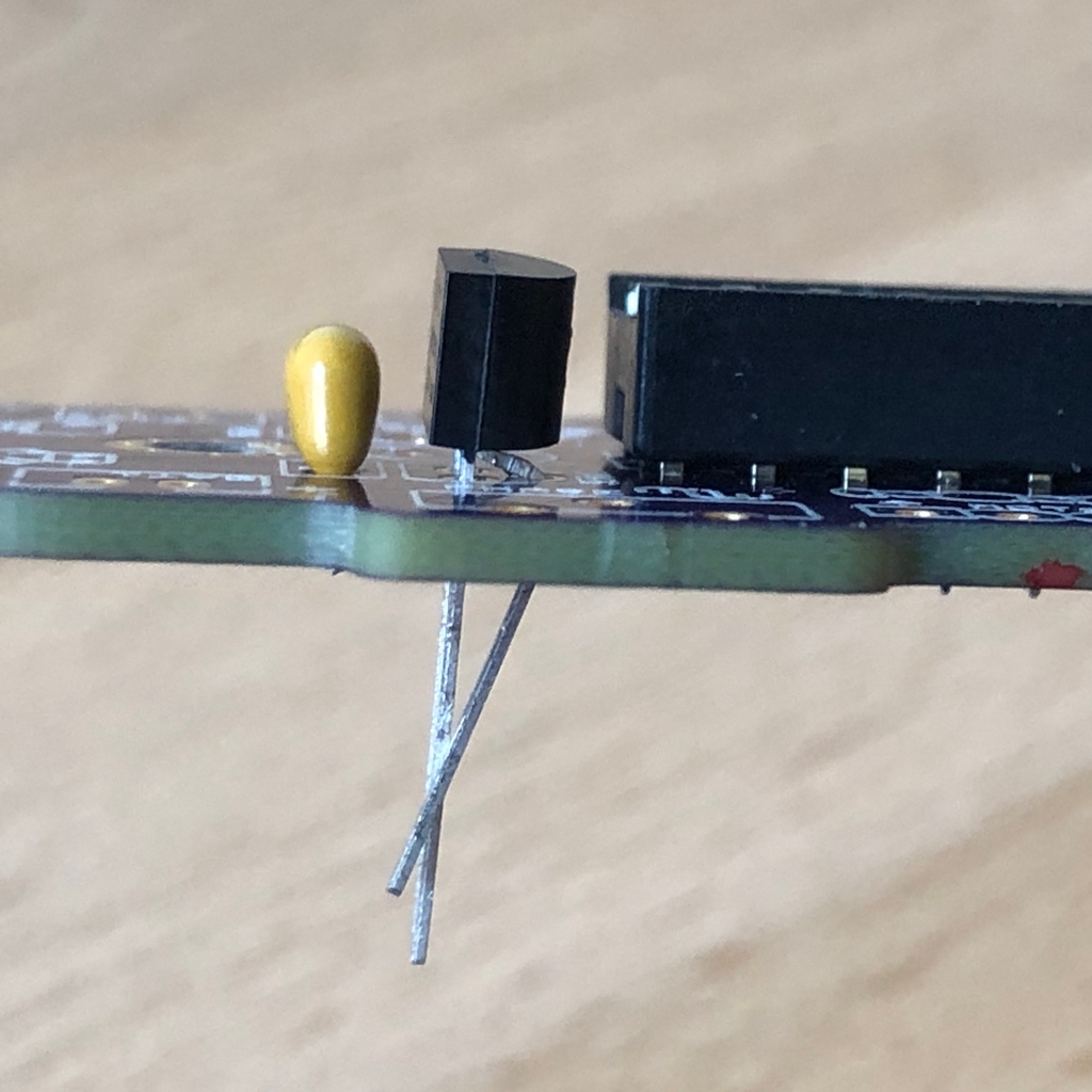
The correct arrangement of the pins is crucial for this component to function correctly. Therefore, make sure that the shape of the component corresponds to the symbol shown on the circuit board. Insert the voltage regulator and push it in bit by bit as shown. The middle leg will bend even more - that’s okay.
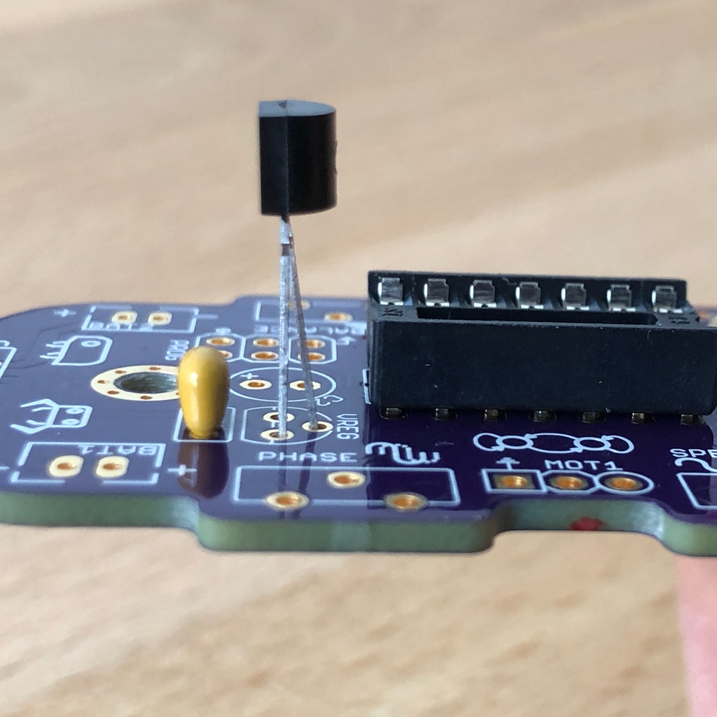

When the voltage regulator is pressed all the way to the circuit board, it should be barely 1 mm higher than the circuit socket. Now solder the three pins as usual and shorten the wires with the pliers after soldering. You will find that the solder joints are very close together this time. Make sure that there is no short circuit.
Well done. Now soldering will be a little easier again, promise.
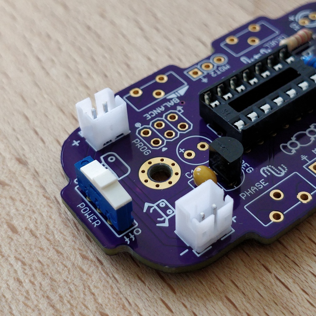
1.6. Battery cable sockets

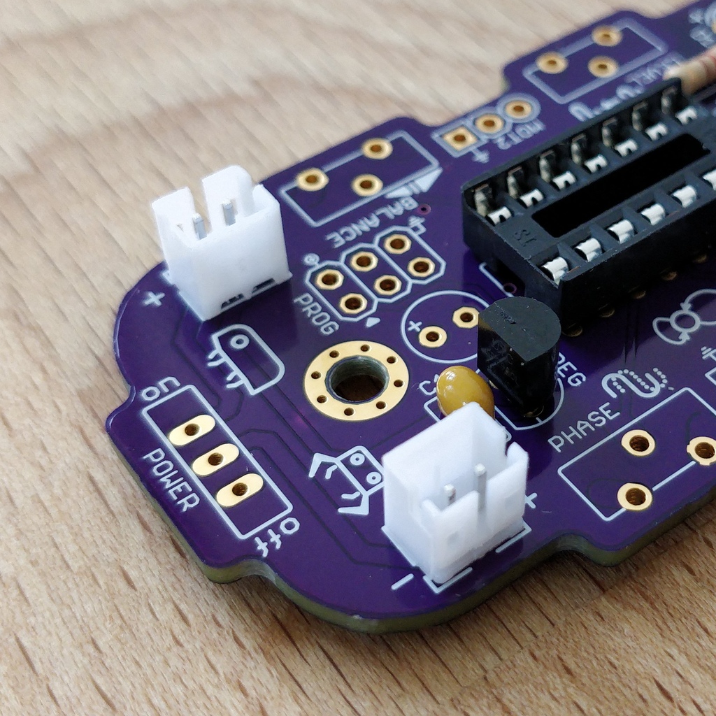
Now insert the two white battery sockets at the markings BAT1 and BAT2. Make sure that you insert them exactly as shown on the circuit board. The small gaps and notches on the sockets are also shown on the board. Correct alignment is very important here!
With a little skill you can insert and solder both sockets in the same operation. Here, too, it is advisable to first solder one pin and correct the alignment again if necessary.
|
Caution
|
Attention! At this point, please compare your circuit board with the photos shown. A battery socket that is soldered the wrong way round will later lead to reverse polarity when the battery is connected and may result in the destruction of parts of your Bakiwi. So better take a second look. |
1.7. Power Switch
Continue with the power switch. It is blue/white and is placed on the board at the POWER marking. You can solder the switch both ways, it works equally in both directions. Just make sure it is in OFF-position so your Bakiwi is turned off when you put in the batteries later.


|
Caution
|
Too much heat melts the switch and can make it unusable, so when soldering make sure to always heat the pin and the surface around the pin at the same time so that the process is short and effective. |
The pins of the switch are quite long and should be shortened after soldering. The material of the switch pins is a bit thicker than usual so you’ll need a little more force to snap them off.
1.8. Pin Headers
Now dedicate yourself to the three pin headers. The two single-row pin headers (1x3) are inserted with the short end from above into the board at MOT1 and MOT2 and soldered to the back as usual. The motors of your Bakiwi will later be connected to them.
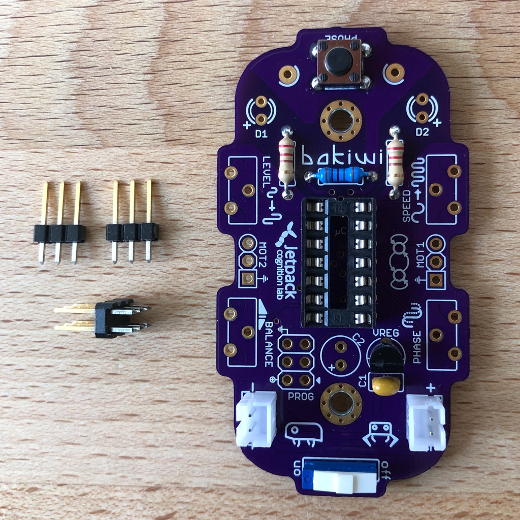
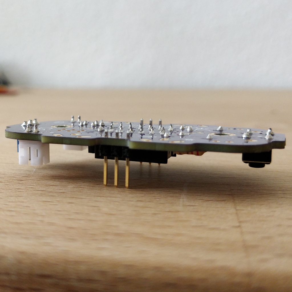
It is best to insert both pin headers together, then turn the circuit board and place it on the somewhat wobbly pin headers as shown in the illustration. Make sure that the pins are as perpendicular as possible to the board. If you first solder only one pin of each header, you can correct the exact position by heating up the solder joint again, in case it should not be straight the first time.
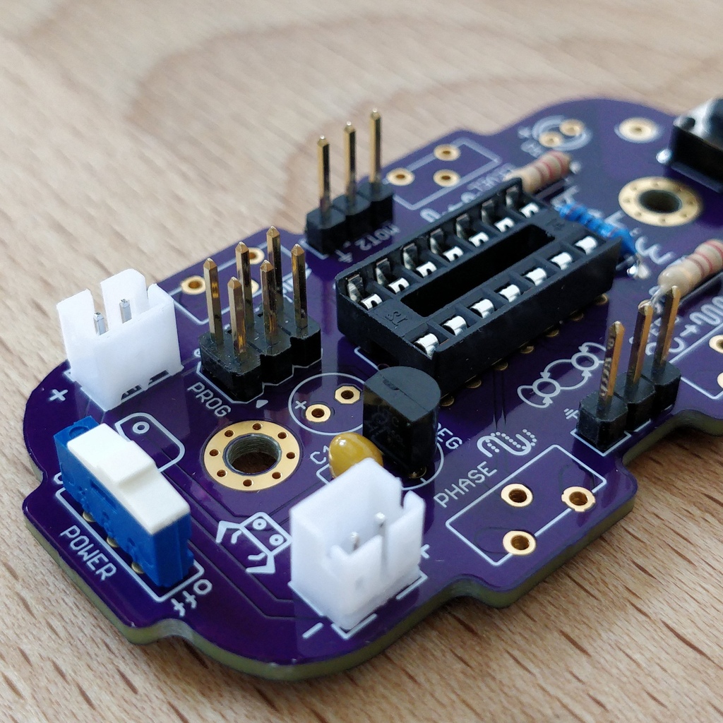
Look for the PROG label on the circuit board and insert the double-row pin header (2x3) with its short end from above. Soldering in should now be easier because the two single-row pin headers now stabilize the board. The double-row pin header is the programming port in case you want to change/update the firmware of your Bakiwi later.
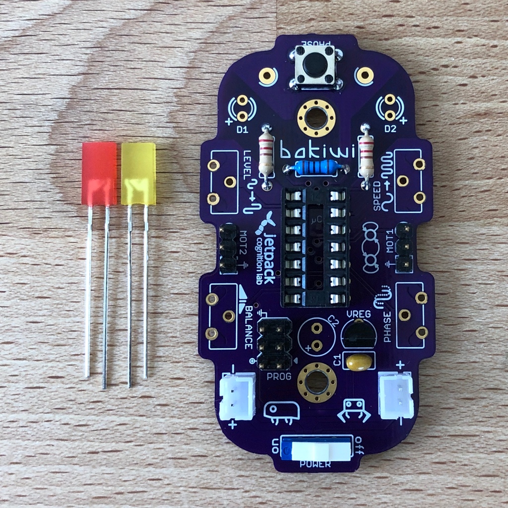
1.9. Light emitting diodes
Your Bakiwi gets two light-emitting diodes (LED) to show you the state of the walking oscillator. The position of both LEDs is marked with D1 and D2. In terms of color, you can decide for yourself which LED should be on which side. You can also use different colored LEDs if you have some.

|
Important
|
Light emitting diodes have a so-called polarity, which means that it does matter how they are installed. Take a look at the pins of the LED. The longer one is always the positive pole, the shorter pin is the negative pole. You can remember this if you imagine that you are mentally disassembling a plus sign and placing the lines one behind the other ( |
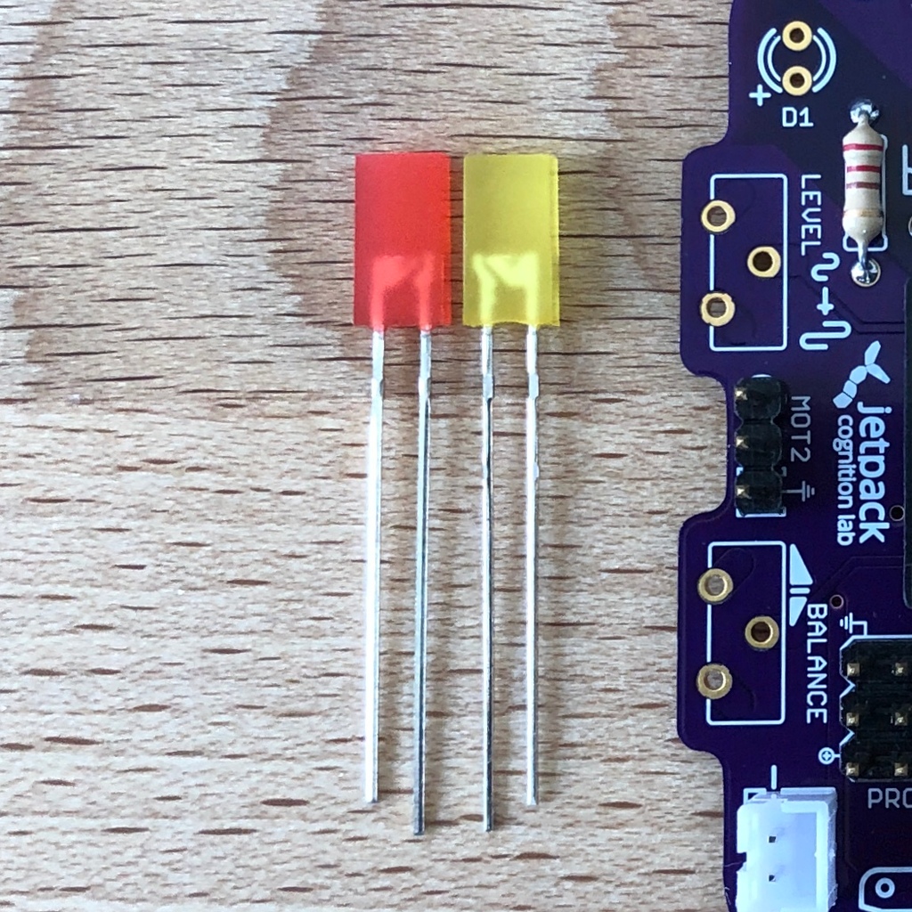
Now insert the LEDs according to their polarity and your desired color and solder them. After that, you can then shorten the pins as usual.
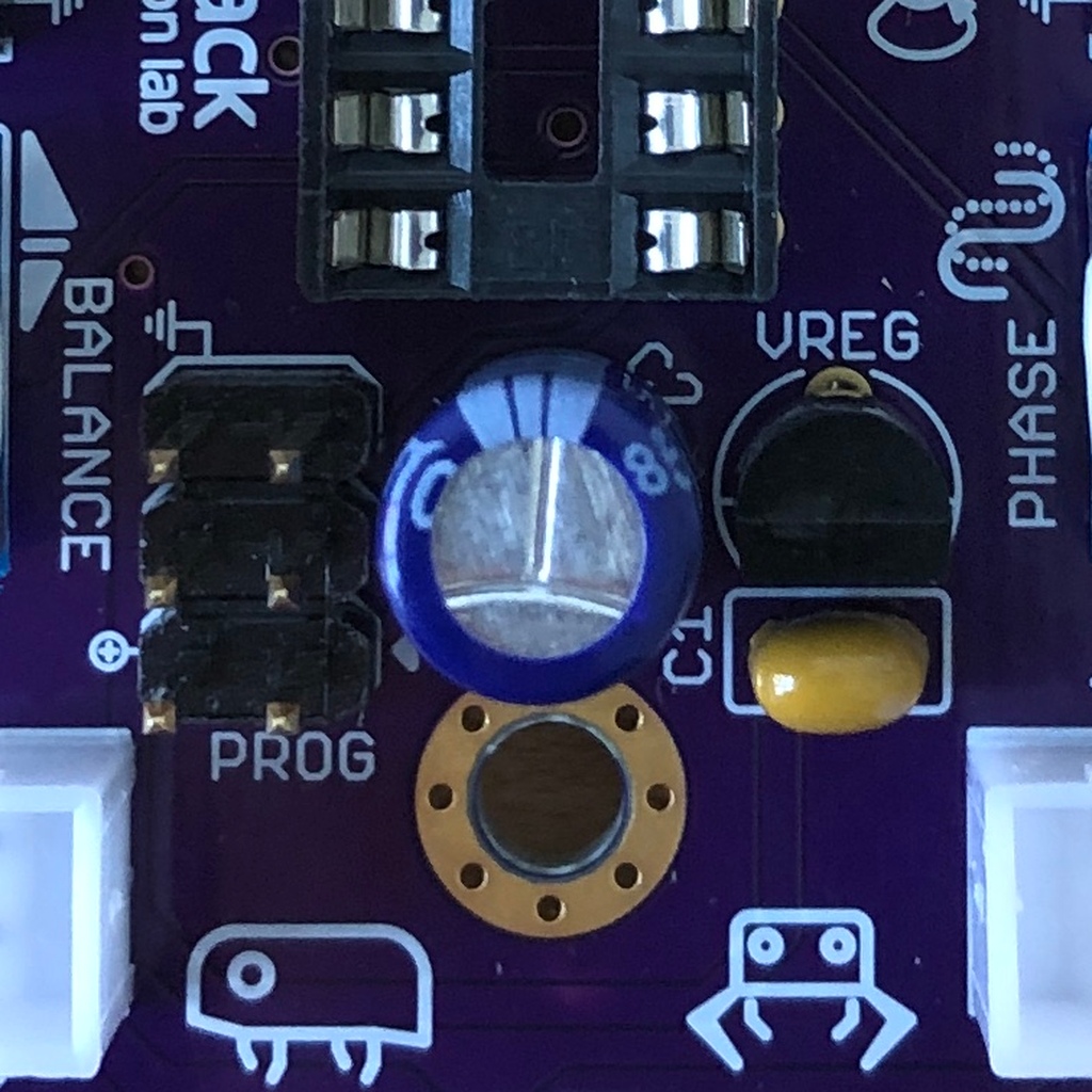
1.10. Electrolytic Capacitor
The electrolytic capacitor is installed exactly as in the previous step (long pin = positive pole). Its position on the circuit board is marked with C2. Make sure to put it in the right way. The negative pole is also marked with a thick (hollow) minus on the cylindrical housing.

|
Note
|
The color of your Bakiwi electrolytic capacitor can differ from the one in the picture, but this does not affect the function. Depending on the manufacturer, the electrolytic capacitors also have a strip of paper that stabilizes the pins. Carefully remove any paper before soldering. |
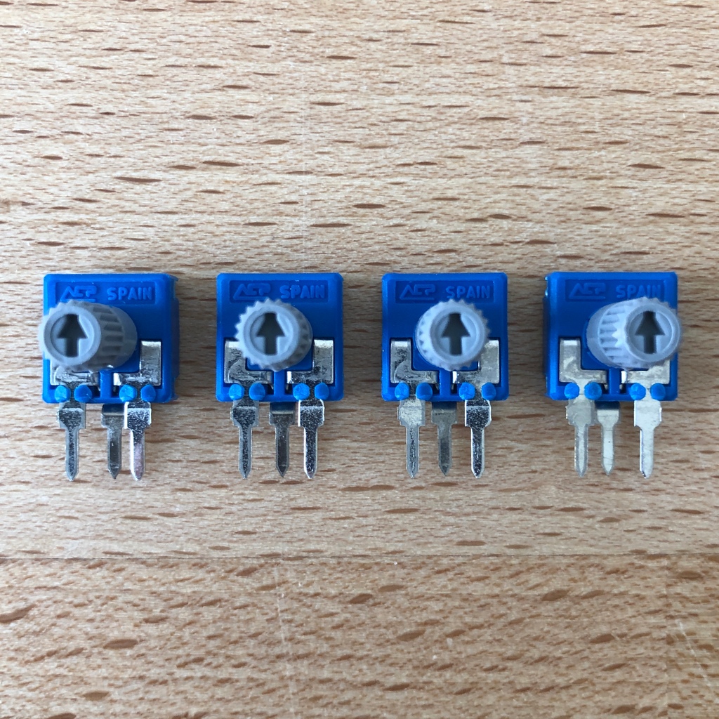
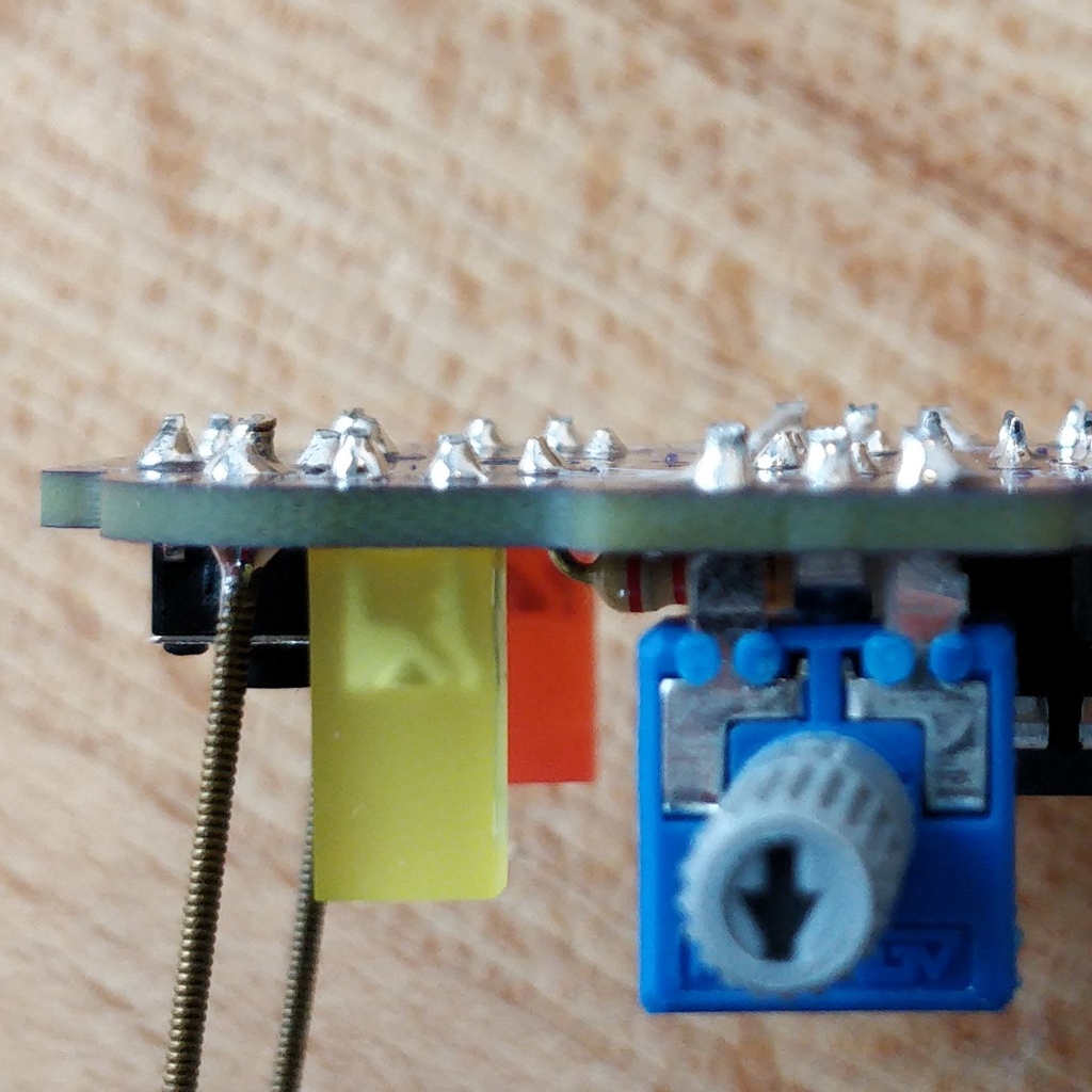
1.11. Potentiometer
Your bakiwi gets four knobs with which you can change its gait. These components are called potentiometers and are adjustable resistors. You know them already from the volume knob of your loudspeakers or other devices.
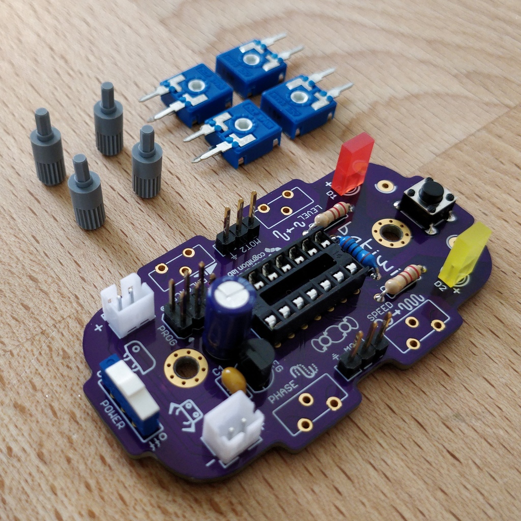

Place the four blue potentiometers with the associated knobs in front of you. Insert the rotary knobs into the potentiometers with the arrows pointing upwards (according to the illustration).
Then put the assembled parts on the positions LEVEL, SPEED, PHASE and BALANCE and flip over the circuit board. The potentiometers are usually quite tight to insert and don’t fall off by themselves.
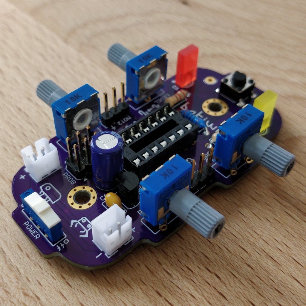
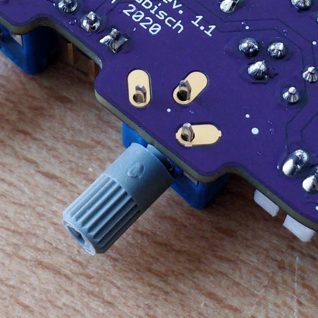
Now you can solder all four potentiometers one by one. After soldering, you should also shorten the pointed ends a little.
Take a Break
You have already soldered a lot of components. If you have worked this far, we recommend that you take a short break. Take care of yourself by getting some fresh air, drinking or eating, and most importantly, relaxing your eyes. Working in the near field can be tiring for your eyes and a little relaxation in between won’t hurt.

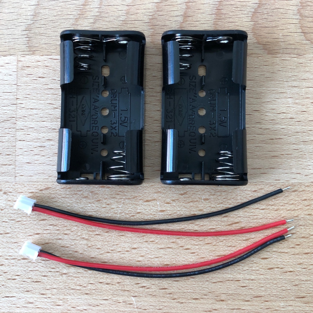
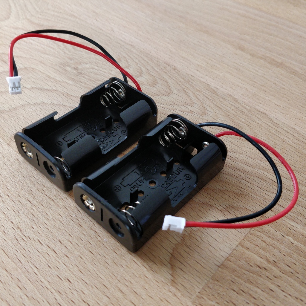
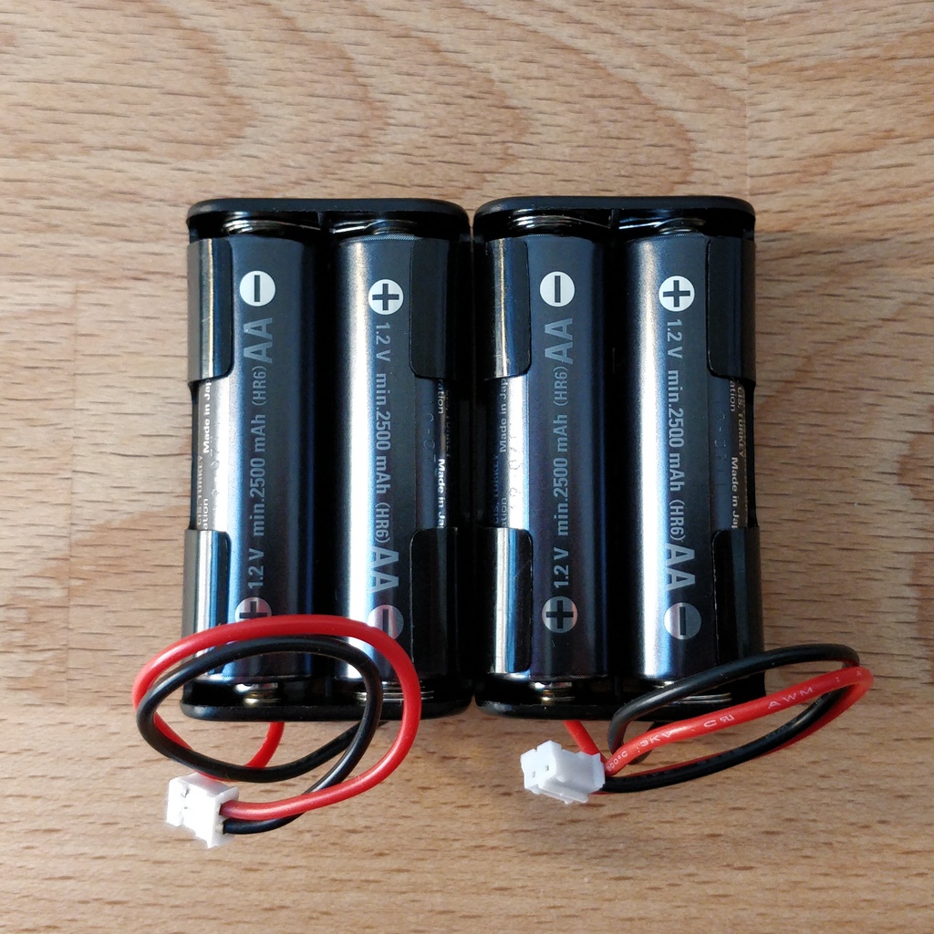
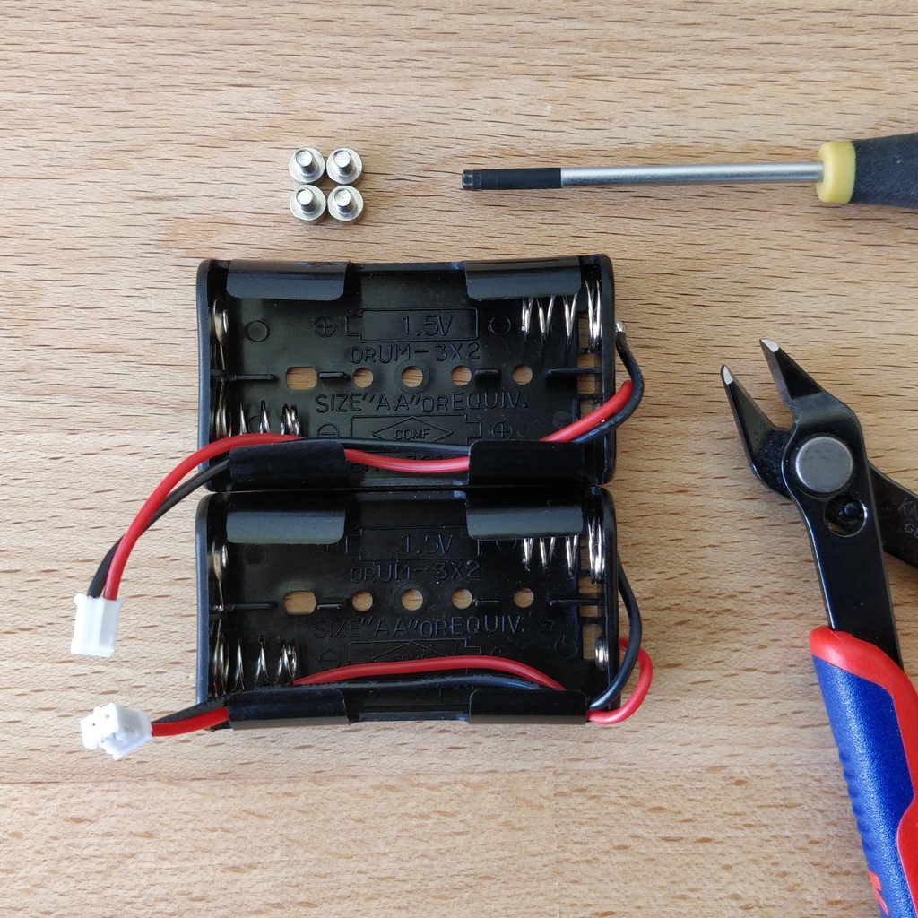
1.12. Battery Compartments
Now you can put the circuit board aside and take the two battery compartments. There is also one red/black cable with a white plug for each compartment.
|
Warning
|
Even if it is tempting: Please do not insert any batteries yet! |
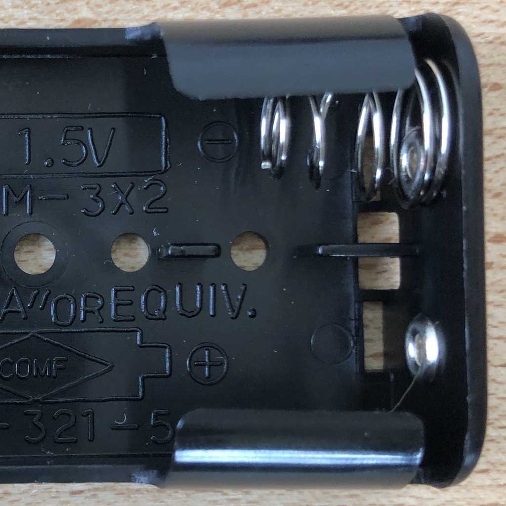
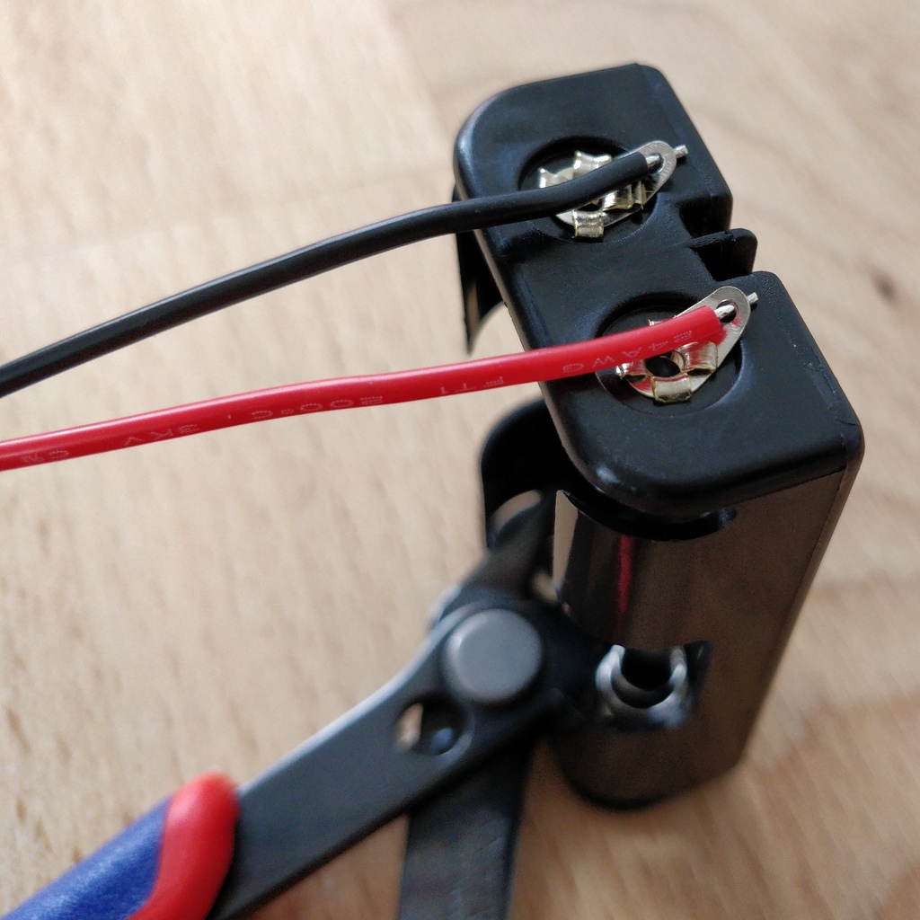
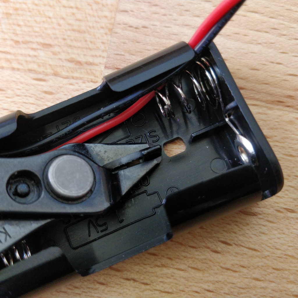
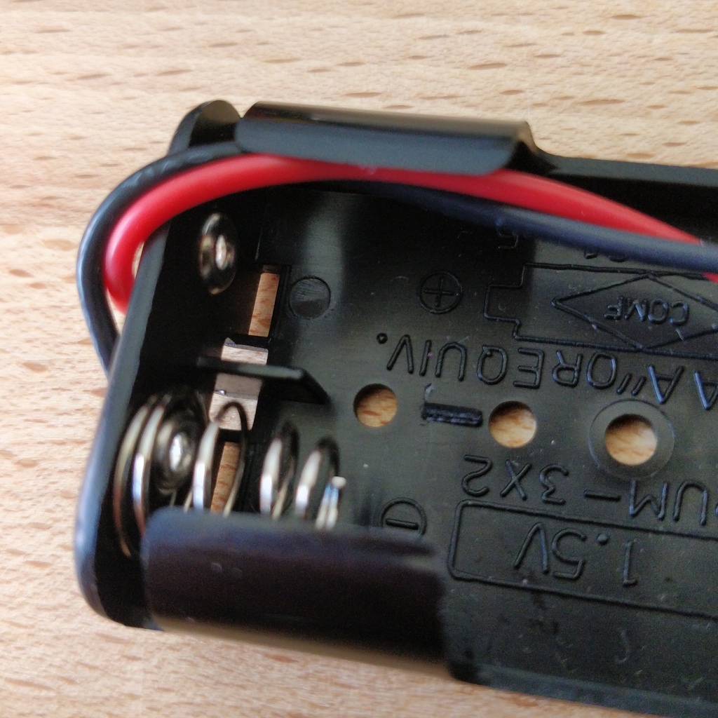
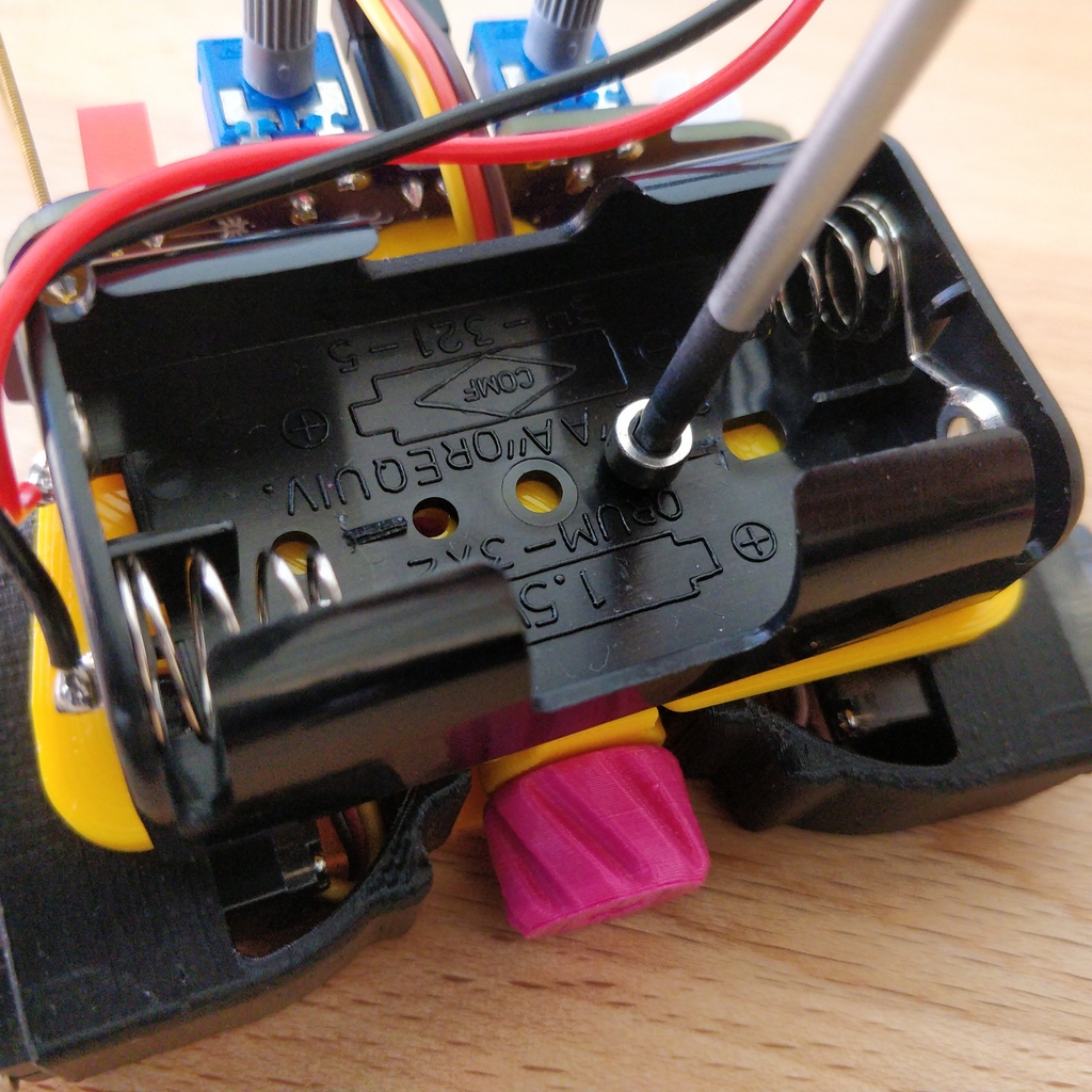
The cables must be soldered to the solder tabs of the battery compartments, for this you can insert the stripped cable ends into the holes. It’s easier if you slightly bend the taps. Make sure the cables are facing away from the flat side of the battery compartment. This will later be the inside where the motors are and you have to avoid the battery cables getting in the way of your Bakiwis legs.
The correct polarity of the cables is of the utmost importance here. The same applies here as for the battery sockets; if plus and minus are mixed up, parts of your Bakiwi can break. The red cable stands for plus the black cable for minus. This convention is widespread and worth remembering. You can read the polarity of the battery compartments on the inside.
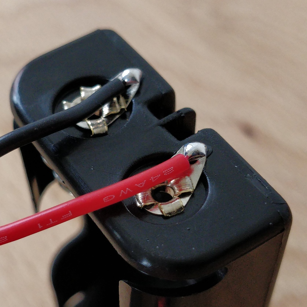
Now solder the inserted cables to the very end of the tab. Solder as efficiently and quickly as possible so that the plastic of the battery compartments does not melt.
|
Caution
|
The plastic of the battery compartments is quite temperature sensitive. Touching the plastic with the soldering iron or heating up the solder tabs for too long can melt the battery compartment and in the worst case make it unusable. |
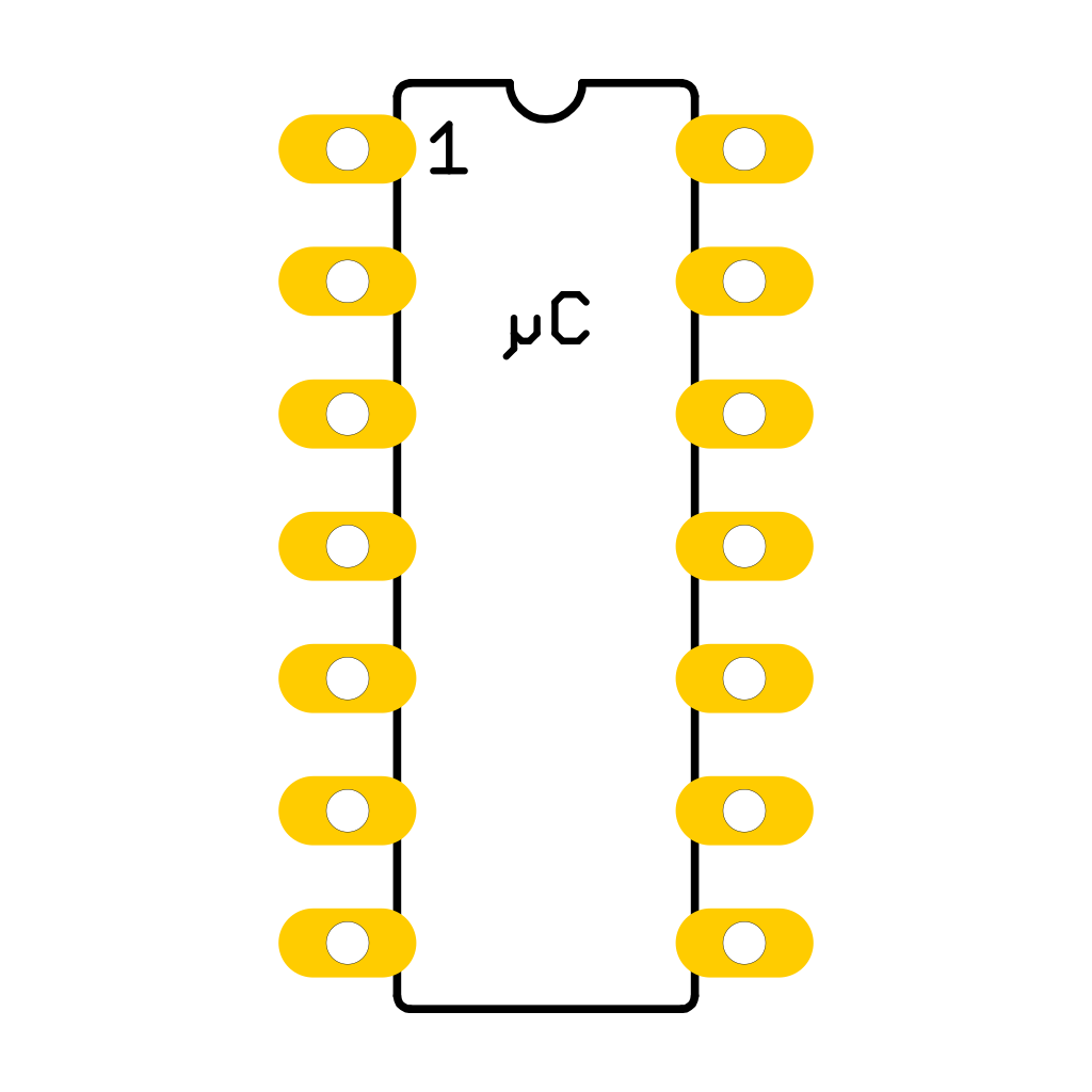
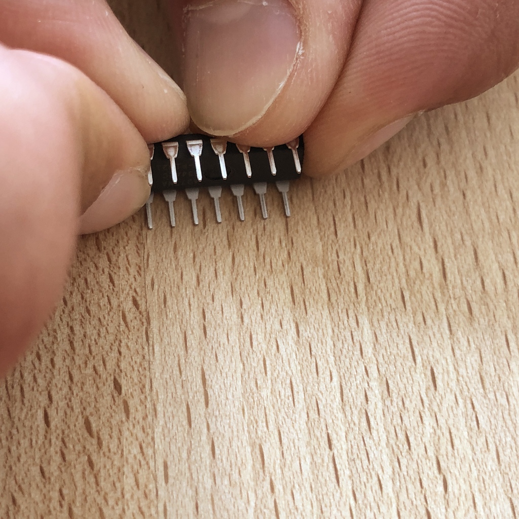
1.13. Microcontroller
The following part does not involve soldering. You can now insert the microcontroller, a so-called integrated circuit (or short: chip) into the socket. To do this, you first have to prepare the circuit with its 14 pins. Hold the chip as shown in the illustration and carefully bend all seven pins on each side a little further inwards. You can use the table top for that.
At first the pins point outwards a little. Ideally, after bending, they point exactly perpendicular to the chip body in the same direction. This makes it easier to insert the chip into the socket.
Now put the microcontroller in the socket, making sure that all pins are in their guides. It is important that the notch on the chip and the notch on the base point in the same direction (towards the Bakiwi-logo).
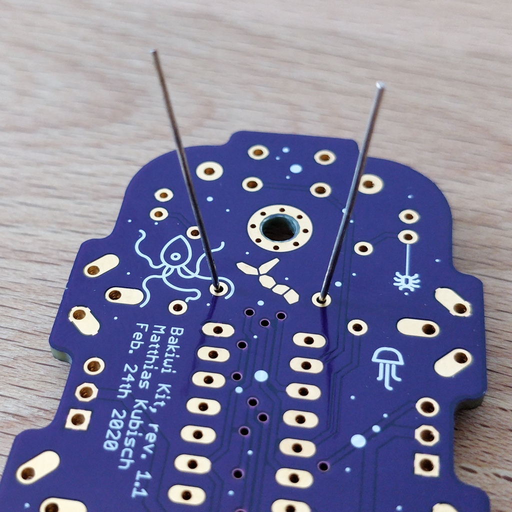
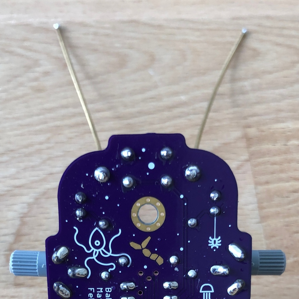
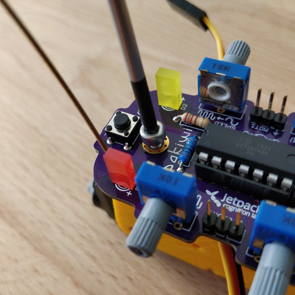
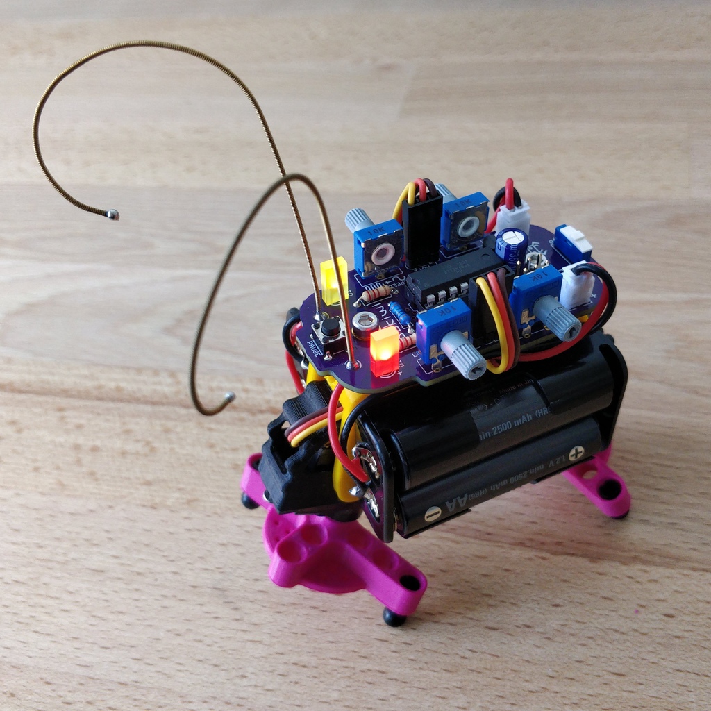
1.14. Antennae
The final soldering step to complete your Bakiwi board is attaching the antennae (feelers or touch sensors). Your kit comes with two short pieces of guitar string. You can use them as antennae for your personal Bakiwi - but you don’t have to. You can use many different metallic materials, e.g.:
-
copper cable with colored insulation
-
brass wire
-
pipe cleaners
-
or something else entirely

The sensors used are automatically adapted by your Bakiwi. It may be that they are not yet sensitive enough or even over-sensitive at the beginning. But after a few minutes, your Bakiwi will be able to use its individually designed feelers just right. So feel free to design, everything is allowed as long as it:
-
can be soldered to the dedicated solder pads
-
is made from mostly conductive material
-
and does not touch any conductive parts of the board
No limits are placed on your creativity.
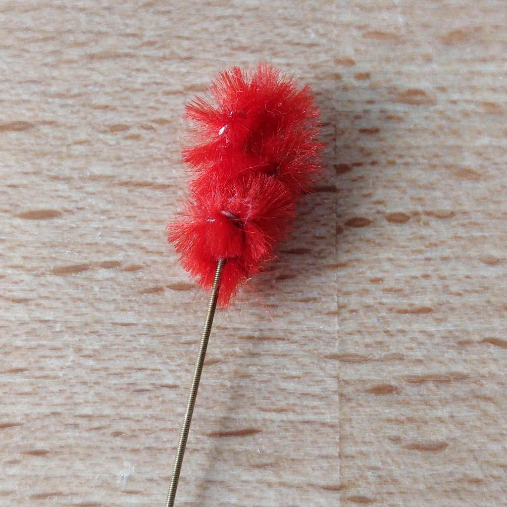
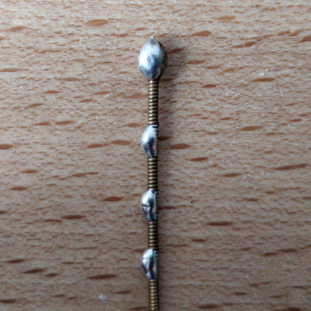
If you don’t have any other materials available, you can also freely rearrange the enclosed guitar strings. You can attach pom-poms or bobbles on their ends. The strings are easy to solder, flexible, conductive and are quite robust and do not kink easily. Here are two examples:
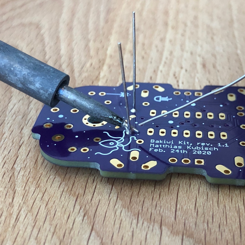
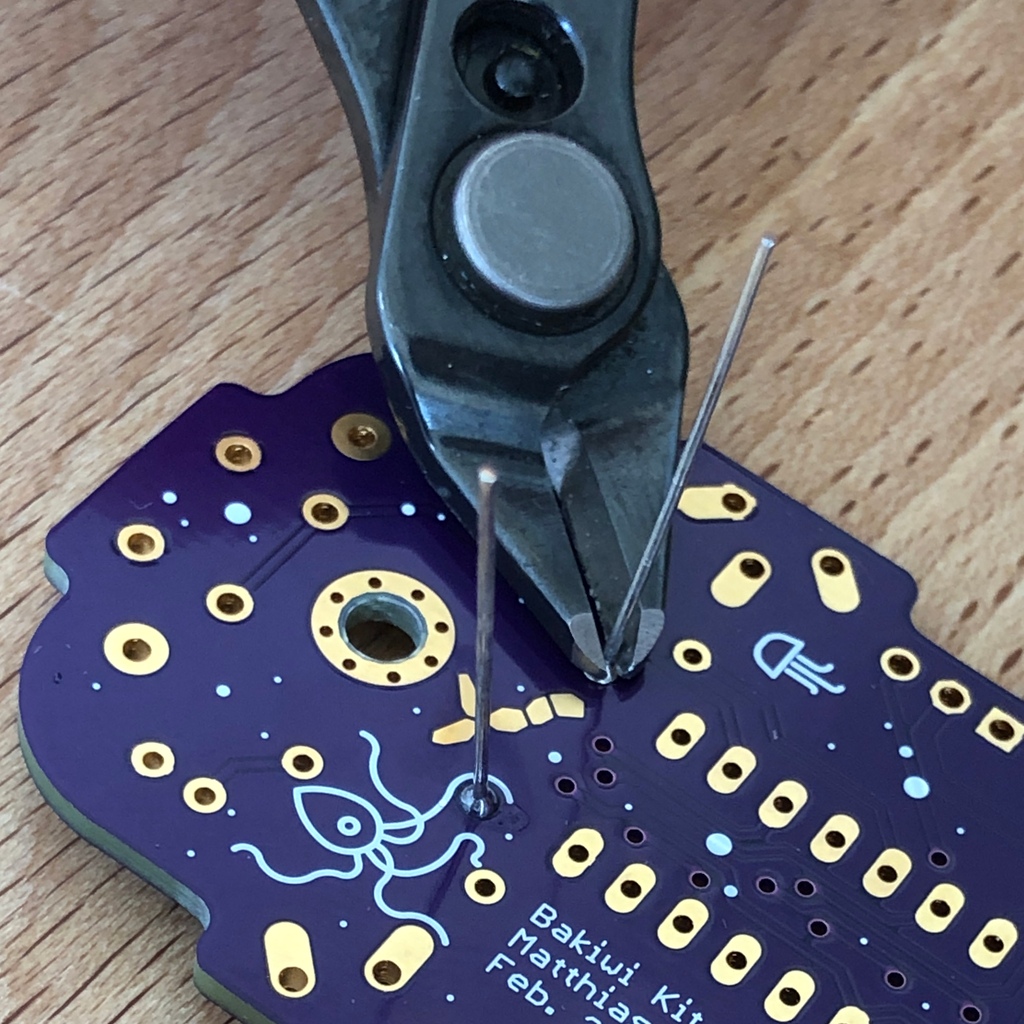
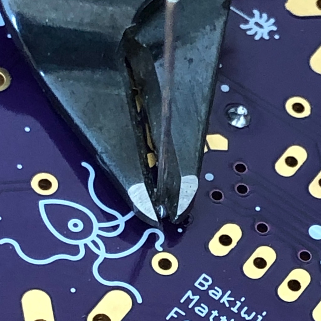
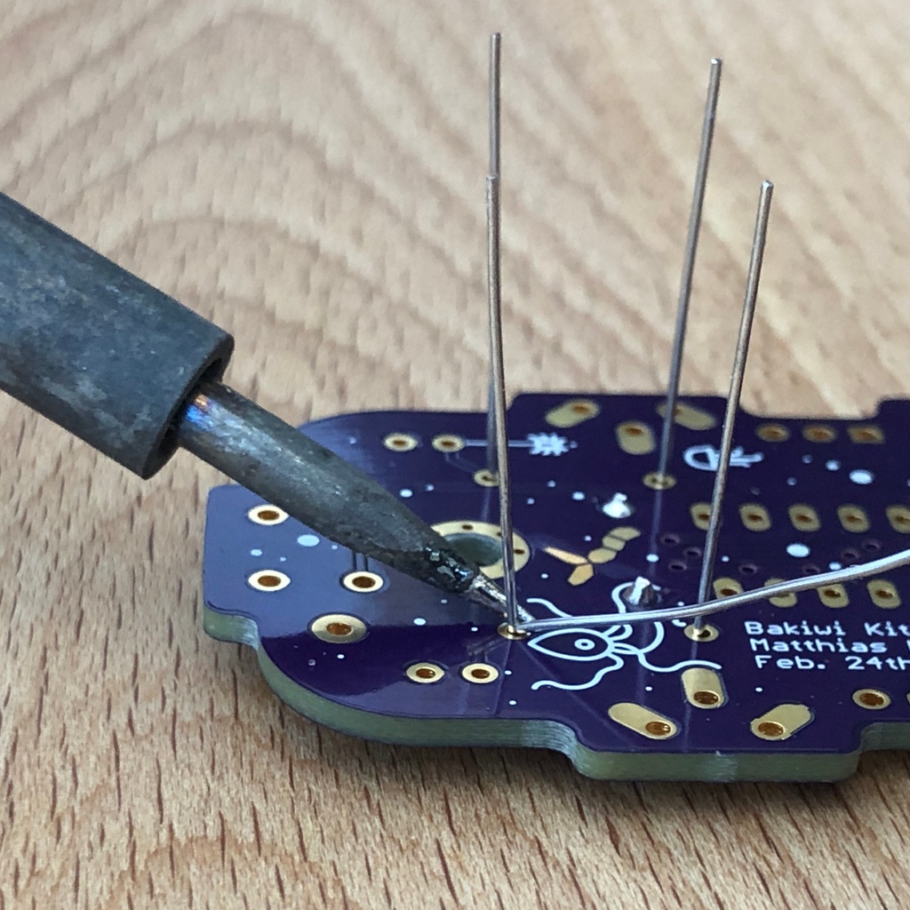
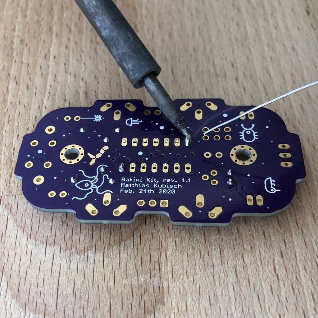
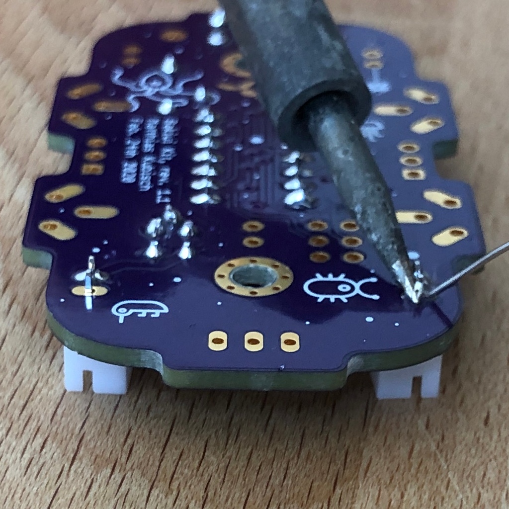
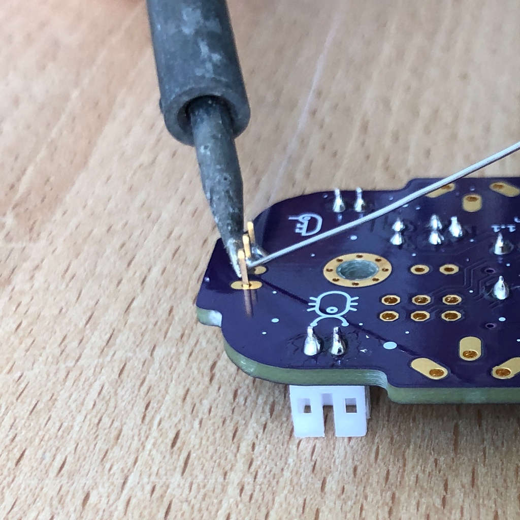
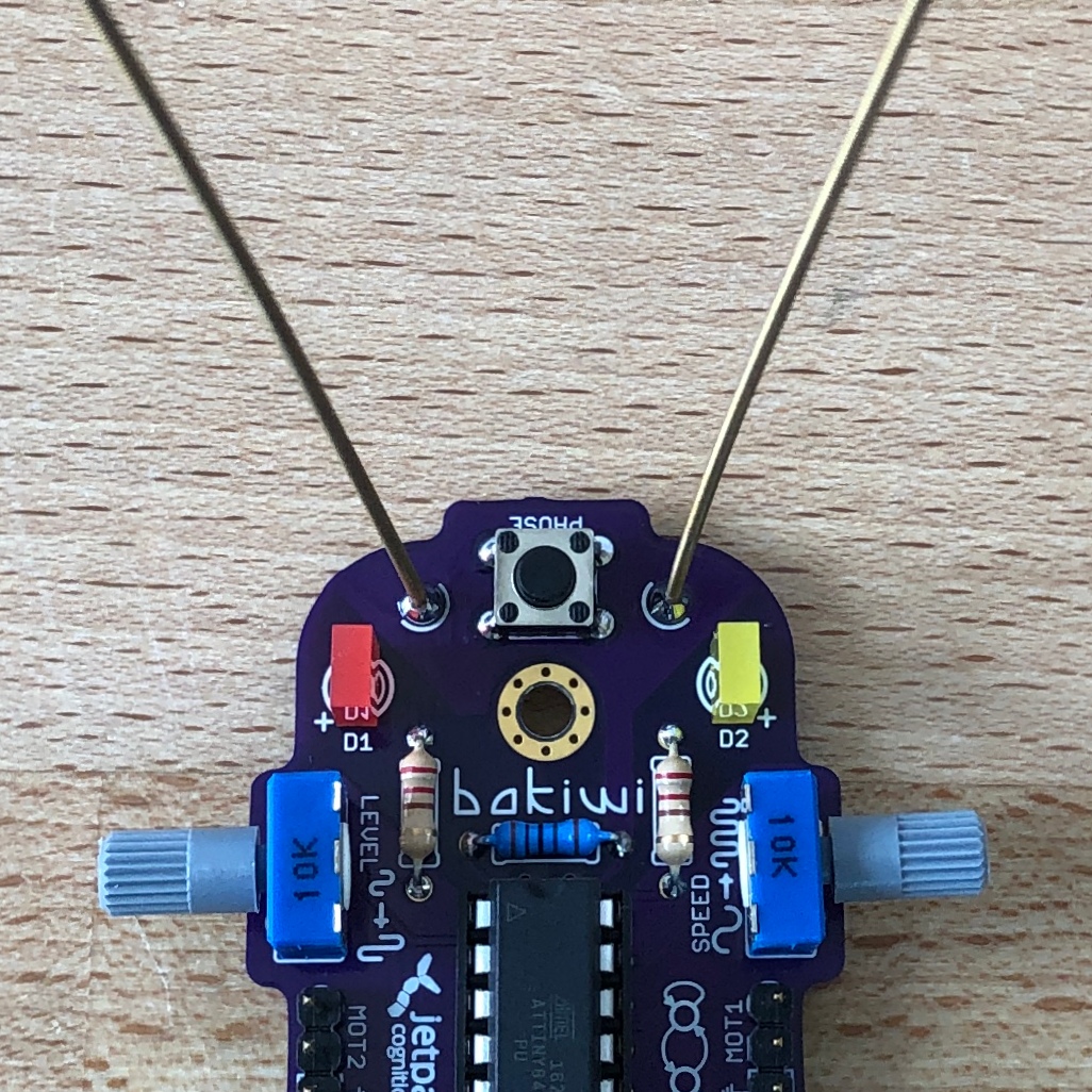
For soldering, place the circuit board with the components facing up on the table and first solder the sensors to the top of the circuit board and then to the back as usual. This gives you better control over their alignment.
|
Note
|
Remember, there may be more metal to heat up for your soldering iron than usual, so you may have to hold the soldering tip on for a few seconds longer. The large soldering areas and the thick wire absorb a lot of heat and get hot, watch out for your fingers! |
2. After Soldering
2.1. Clean Up
Drum roll…. cymbal strike. You’ve done it. The soldering work is now complete. The soldering station is no longer needed and you can turn it off and let it cool down.
|
Warning
|
The solder tip can be very hot for a few minutes after it has been switched off. So let the soldering station cool down for a while before you put it away. |
Finally, we recommend equalizing the solder joints on the back again and shortening the remains of the pins that are too long. This is important so that after the mechanical assembly there are no more pointed pins that could dig into the motor or battery cables.
2.2. Waste Disposal
We tried to design the kit so that there is as little waste as possible. Please separate the waste and recycle. All small metal residues can be disposed of as packaging waste and the scraps of paper as waste paper. If you like, you can reuse the enclosed zipper bags and the cardboard box or dispose of them as packaging waste or waste paper.
2.3. Testing
In case you have a multimeter at hand: Before the mechanical assembly begins all electronic components should be tested. This way you could identify potential short circuits.
2.3.1. Short Circuit Test
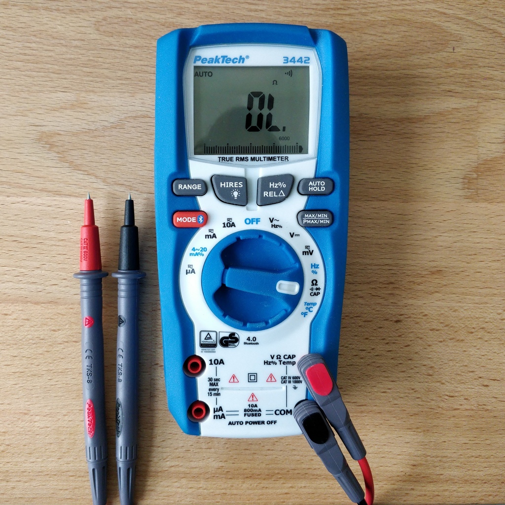
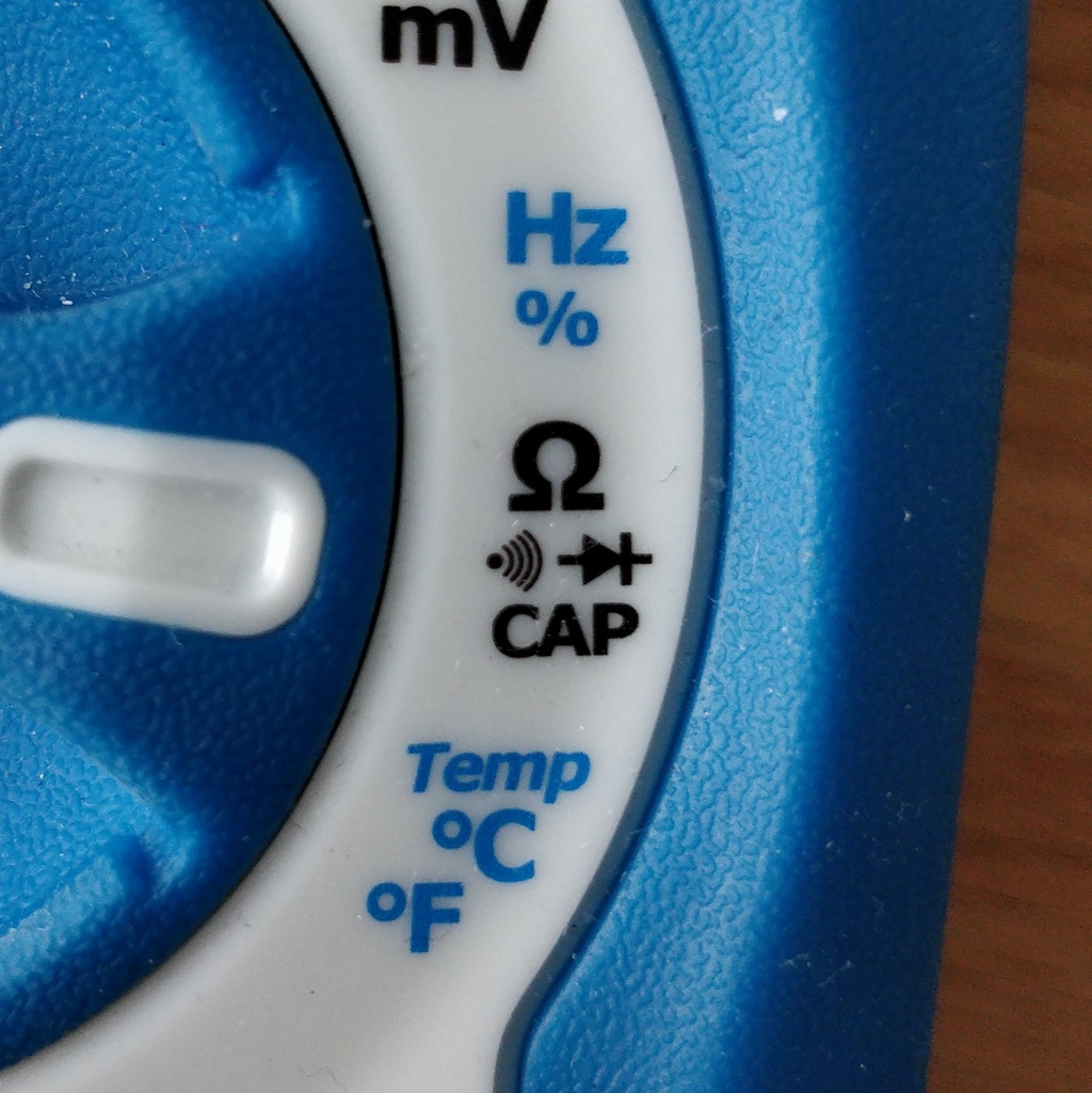
Take a multimeter and switch it to continuity test mode ("beeper"). You can recognize this by the loudspeaker symbol. Hold the two test probes with the metallic ends against each other and make sure that there is a clearly audible beep. The beep sound signals an electrical contact with no significant resistance in between. You can use it to check solder joints, cables and plugs for proper contact or to find unwanted short circuits.
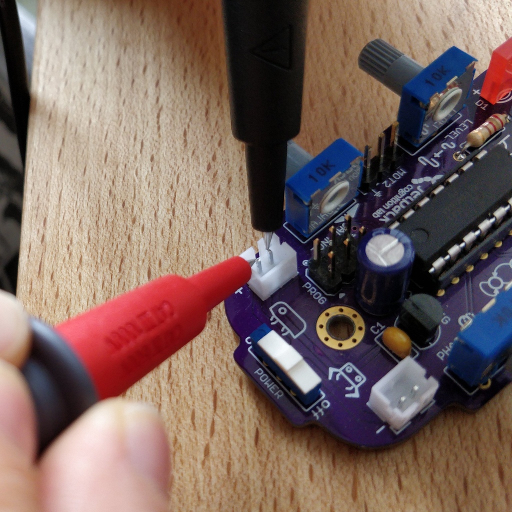
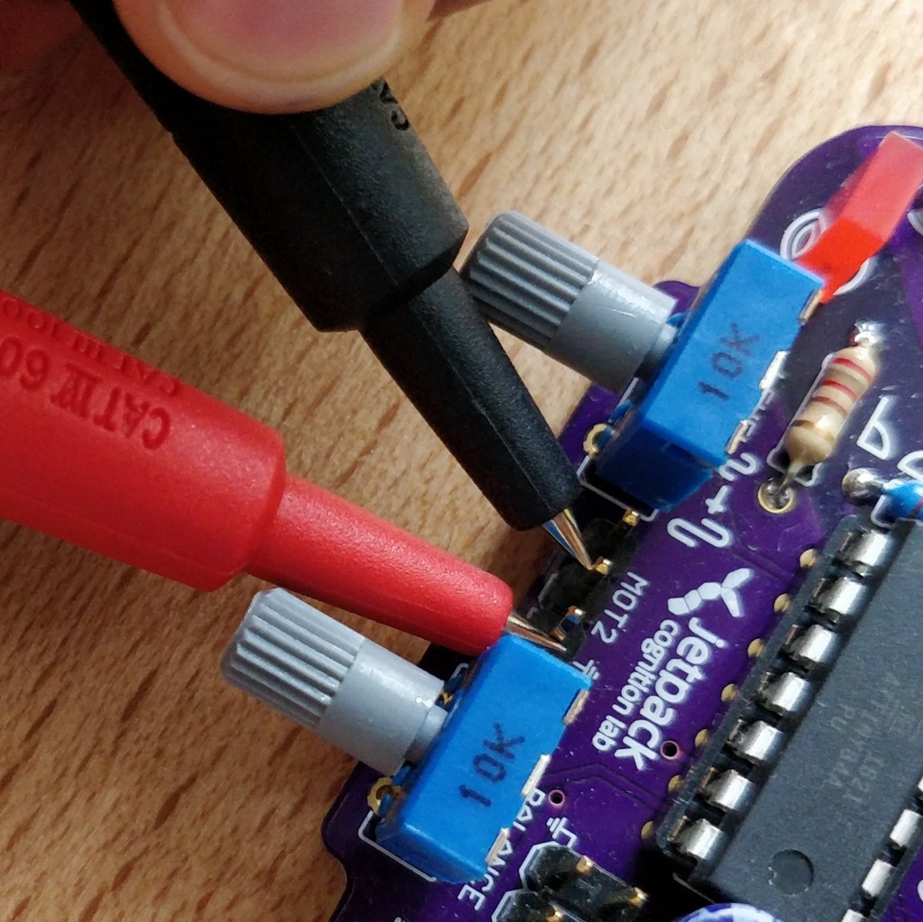
Now hold the test probes on the two pins of the left battery socket. No signal should sound here. Repeat the test with the other socket. Also test the pins of the two motor connections and the 6-pin programming port by checking each two adjacent pins for short circuits. If there is a beeping for two pins, you have to look very carefully at your solder joints at this point. It is possible that some solder has gotten between the solder joints and is connecting them. Make sure there is enough light during the inspection and, if necessary, use a magnifying glass.
|
Tip
|
If two solder joints are accidentally connected with solder, you can try to separate them by reheating them. If the solder looks sticky, try adding some fresh solder (with flux that has not yet evaporated) to make the solder joints workable again. The colored varnish (blue or purple) on your circuit board will not accept solder and will help you separate the solder joints. If both joints are heated up together and have sufficient flux, they separate easily from each other and retreat to their solder pads. Optical inspection can also rule out many possible sources of error. A good solder joint always looks a bit like a small volcano or mountain, if the solder joint looks more like a ball, this can be evidence that too little solder has landed on the pad. In this case the contact might be not reliable. |
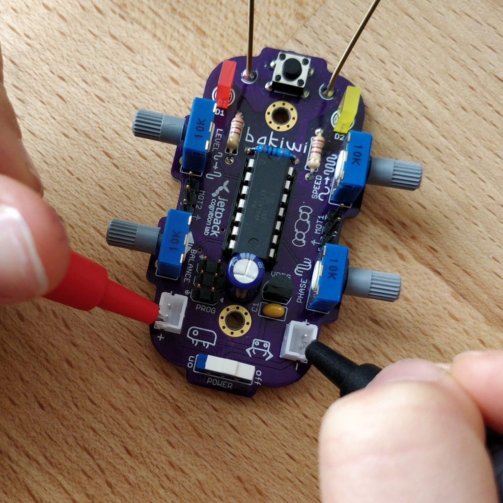
Finally, test the positive pole of the left battery socket against the negative pole of the right battery socket. There should also be no contact to be measured here. Set the power switch to ON and measure again. There should now be a contact and you should hear a beep when measuring. Now turn the switch back OFF.
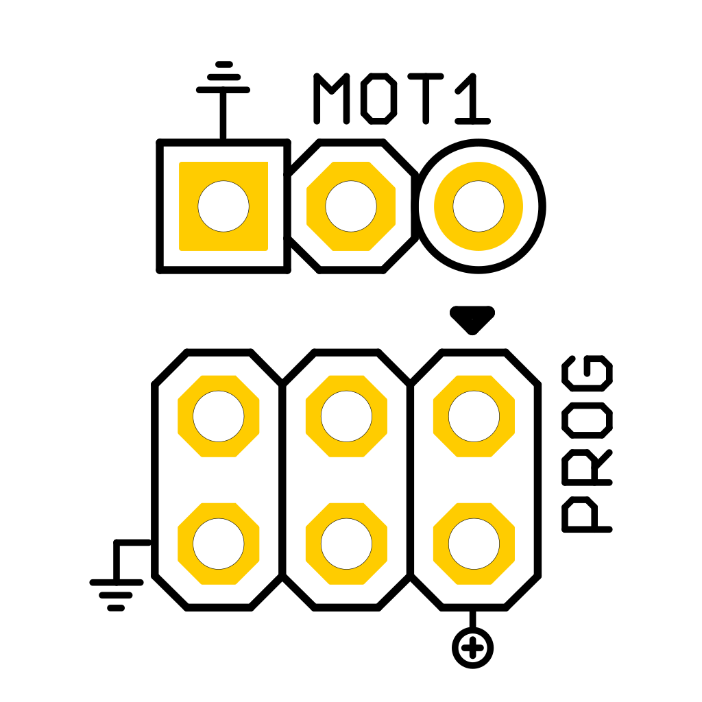
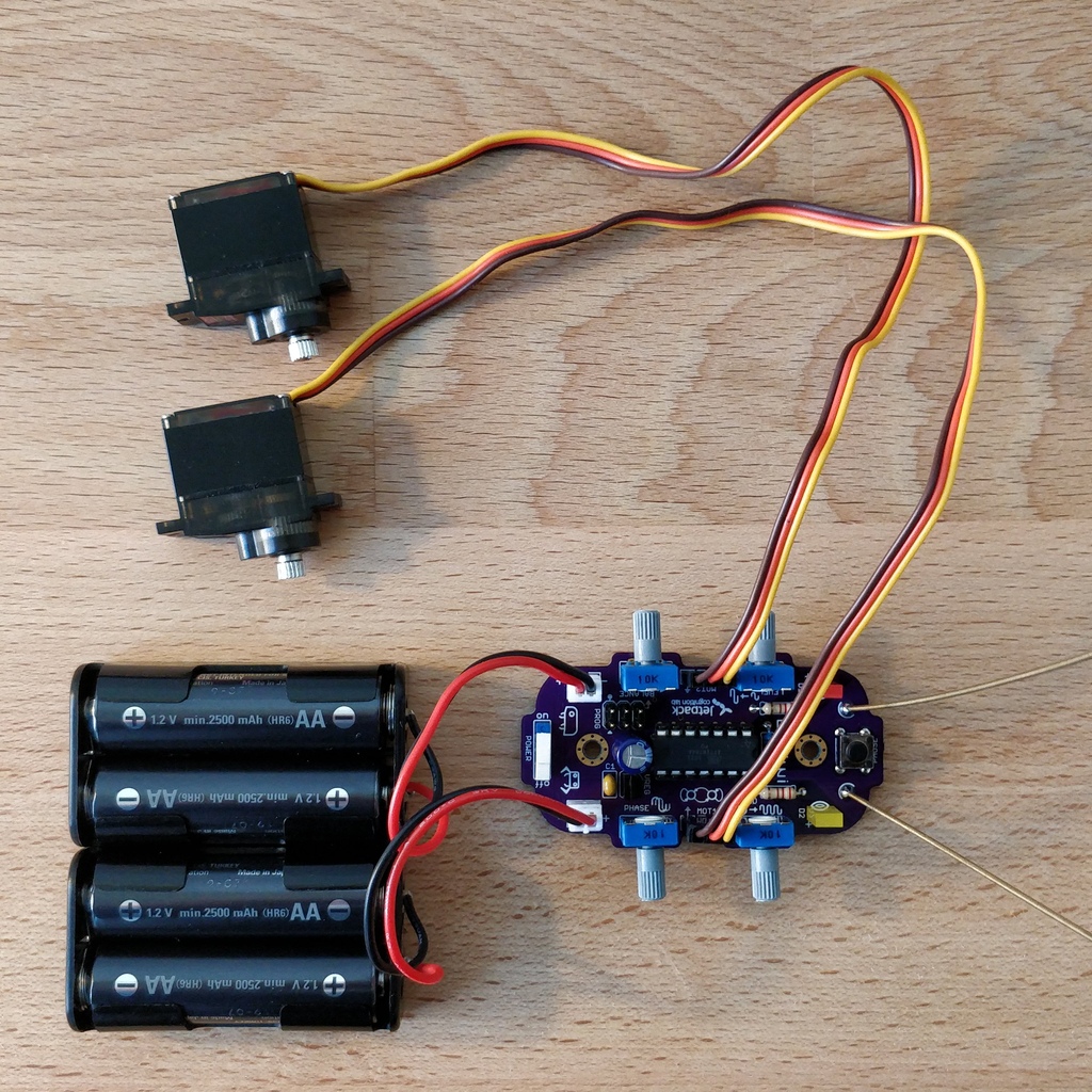
2.3.2. Connect Motors
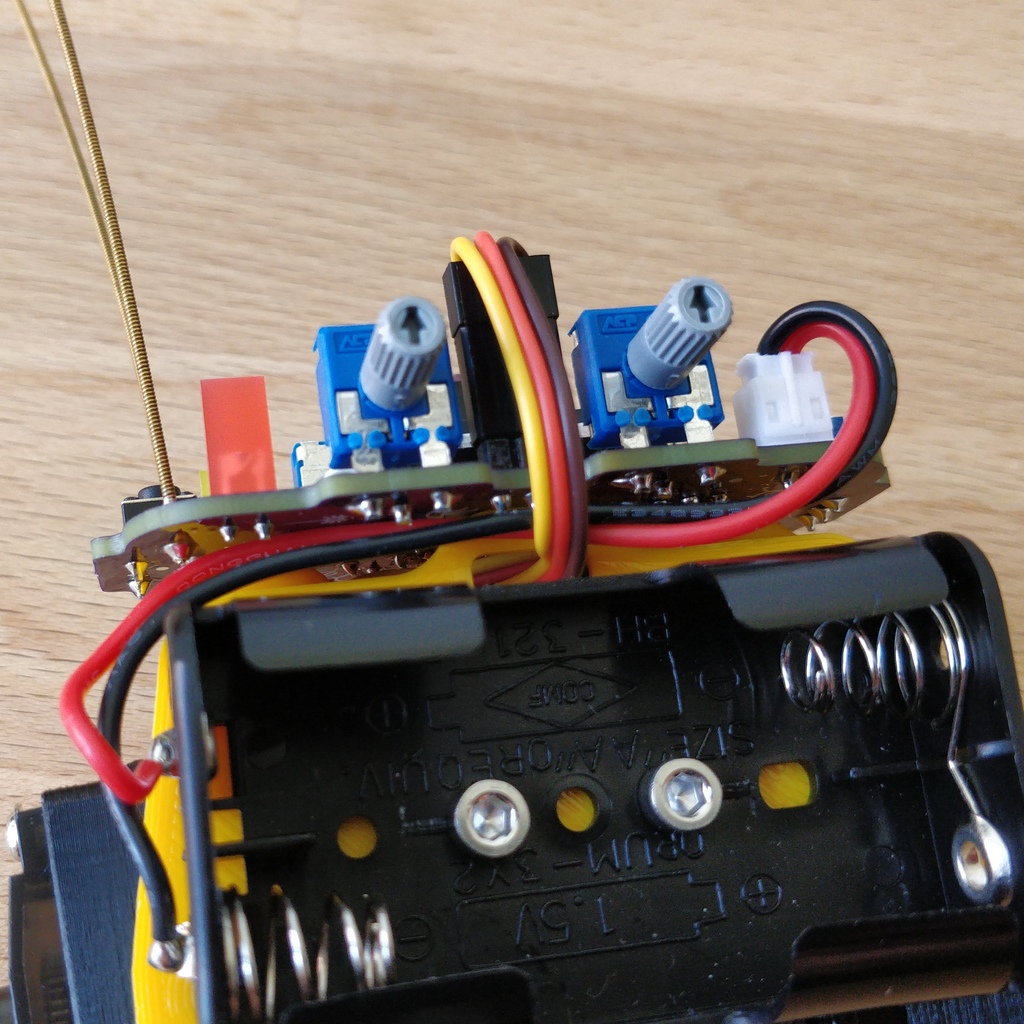
Now connect the motors. Make sure that the brown (or black) wires of the 3-wire motor cable are connected to the pin that is marked with the ground symbol on the circuit board (see illustration).

Now insert the batteries. It is very important to note the polarity (+/-) displayed inside the battery compartment. The plus and minus symbols can also be seen on your batteries or rechargeable batteries. Now connect the battery plugs to the sockets on the circuit board, it doesn’t matter which compartment you connect to which plug.
|
Warning
|
Watch out! If the batteries get warm or even hot after connecting the compartments, you have to disconnect the connector from the circuit board immediately. The heating up of the batteries very likely indicates a short circuit and you will have to repeat the electrical continuity test again and carefully inspect your solder joints to find the short circuit. |
Now turn ON the power switch and if everything is put together correctly, you should already see the diodes flashing. When all rotary knobs with the arrows point upwards, the LEDs should flash in unison.
If the diodes work, press the button and immediately afterwards both motors should start making noises and turn the shafts (the round toothed metal ends).
Touch the feelers with your hands and the noises of the motors should immediately change, slow down or even stop. When the sensors are released, the motors should resume their original behavior. Now turn your Bakiwi off again.
If everything works as expected so far, you can now move on to the next chapter, the mechanical assembly.
If only one motor works but the other does not, make sure that all knobs are pointing up and that the motor cables are connected as described in the section Connecting Motors.
2.4. What to do when something is broken?
If you should have lost or broken a component during soldering or assembly: Don’t panic! We’ll be happy to send you a new one. Send us a letter with the broken part and a return envelope addressed to you and we will arrange for a replacement immediately. We would be happy if you take the time and briefly describe to us how the component broke so that we can improve our Bakiwi kit with your help.
If there is a problem but you are not entirely sure what is causing it, you can also send us photos of the board (e.g. from the top and bottom side) and we can try to help identify the source of the error.
3. Mechanical assembly
3.1. Preparation
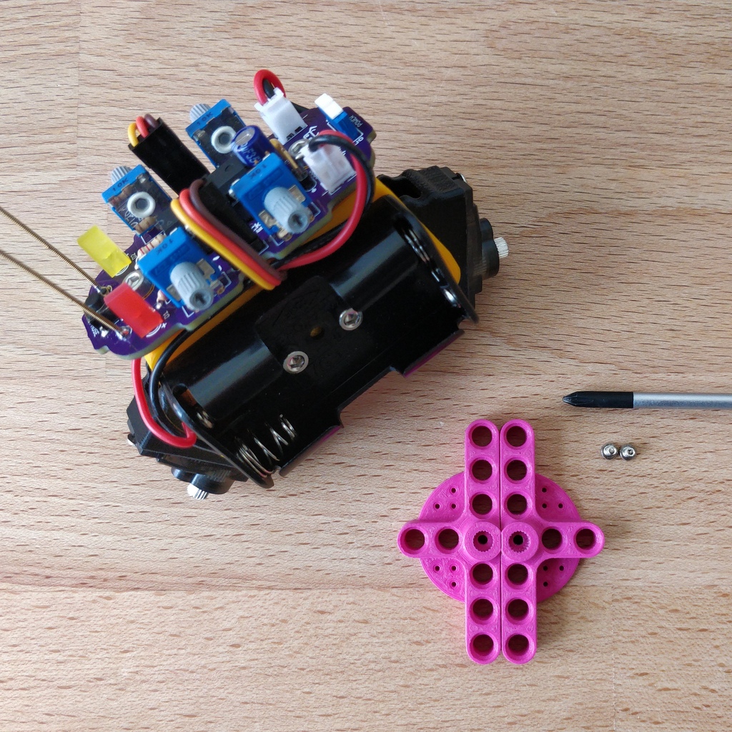
Take the illustrated mechanical components out of the package and place them in front of you. You have already prepared the Bakiwi circuit board and the battery compartments in the previous work steps.
You will need additional tools for the assembly: a small Phillips screwdriver and a hexagon socket screwdriver (2.5 mm). If available, tweezers may be useful and simplify the assembly, but they are not strictly necessary. The side cutter is also required again.
3.2. Install Motors
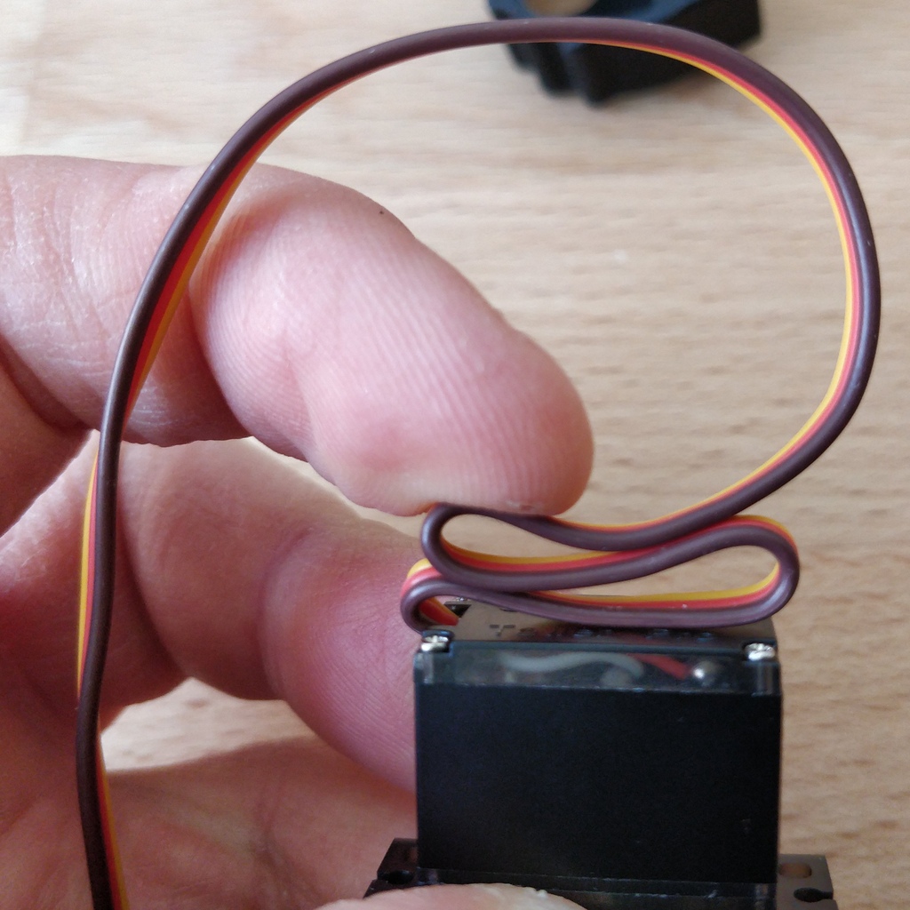
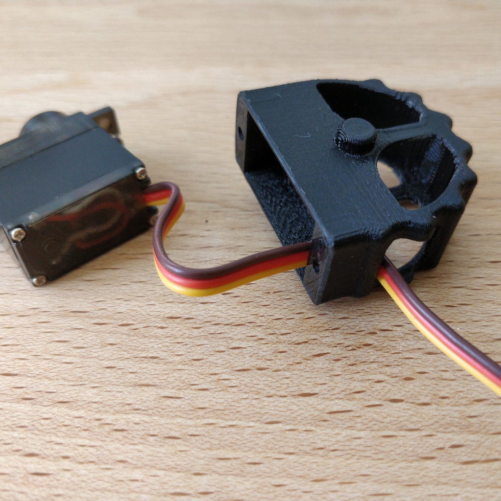
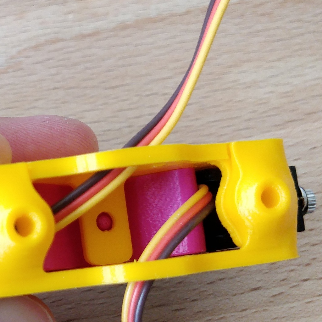
We start our mechanical assembly with the motors. To do this, take one of the motors and a motor holder as well as two of the four Phillips screws (you can recognize them by the fact that they are the only ones with tips). Fold the motor cable a few times, as shown, and squeeze it gently so that it falls into the same folds more easily when you install it.
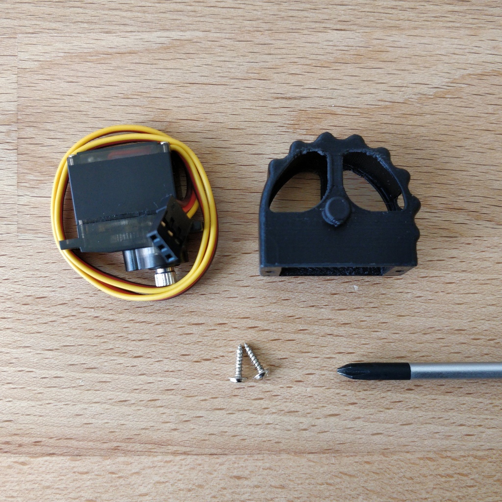
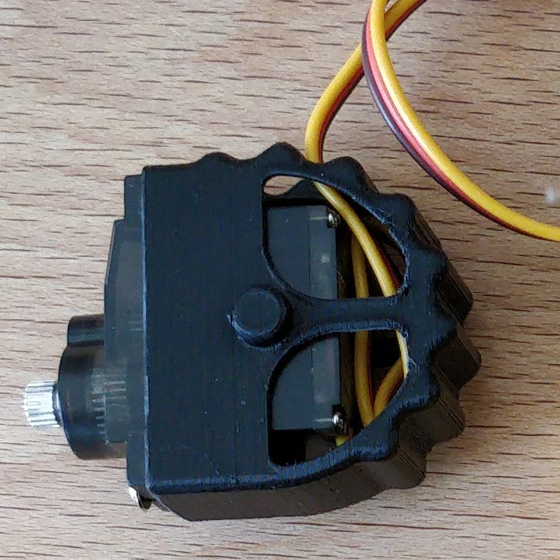
Thread the motor cable through the large opening in the holder and out of the holder again through the small opening on the side. Now insert the motor into the holder. Make sure that part of the cable is folded in the holder so that less of the cable protrudes overall. The shaft of the motor should point away from the small opening (compare your result with the picture).
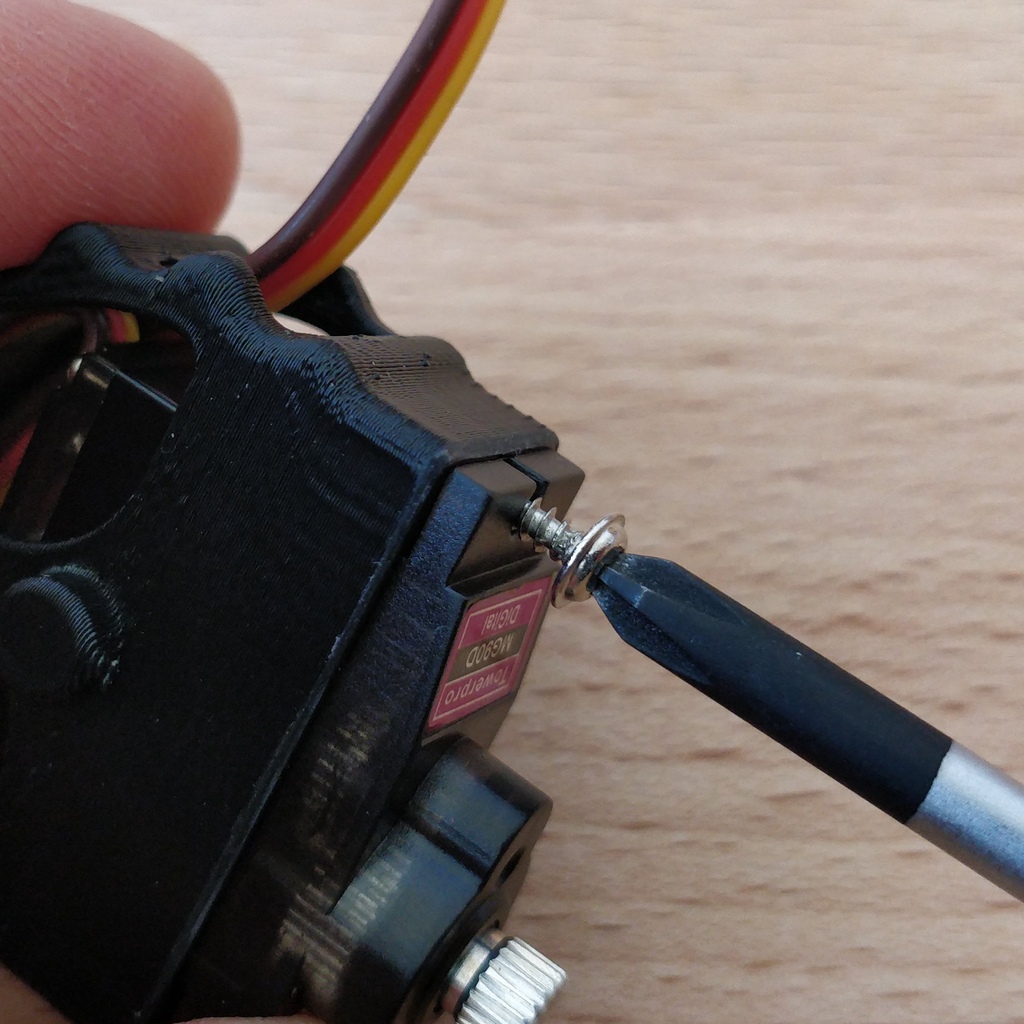
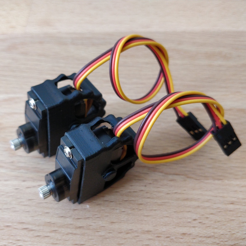
Now insert the screws one after the other and tighten them sufficiently. If everything is in place, repeat the steps with the second motor.
3.3. Putting the frame together
Next, put the frame together. To do this, place the base plate of the frame in front of you and place the V-shaped clamp nut between the two central hole bars. Insert the locking screw and tighten it two turns.
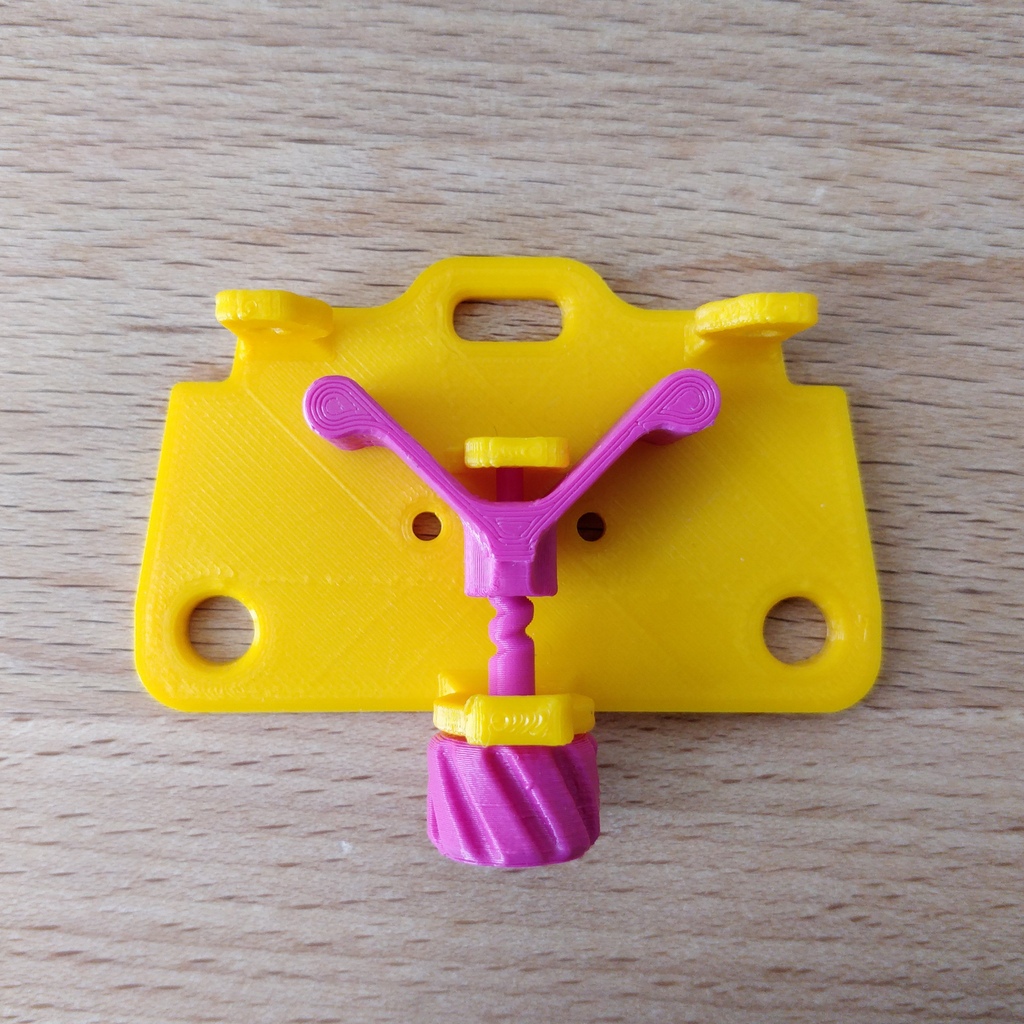
Place the two motor holders with their axle ends on the holes in the base plate. Make sure that the openings and protruding cables are facing up. Now put on the lid of the frame and hold everything together with your fingers. If you gently tighten the locking screw a little further, the frame will hold together better.
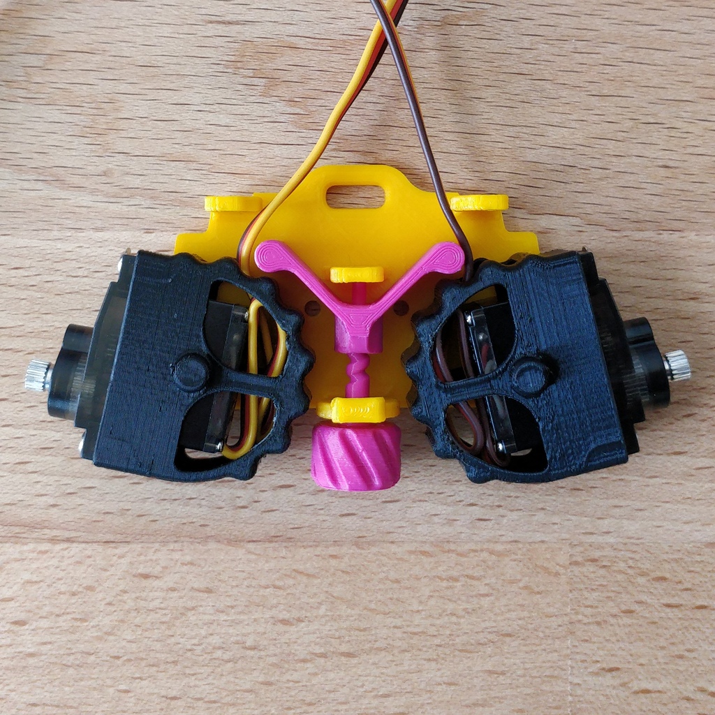
3.3.1. Thread and stow the cables
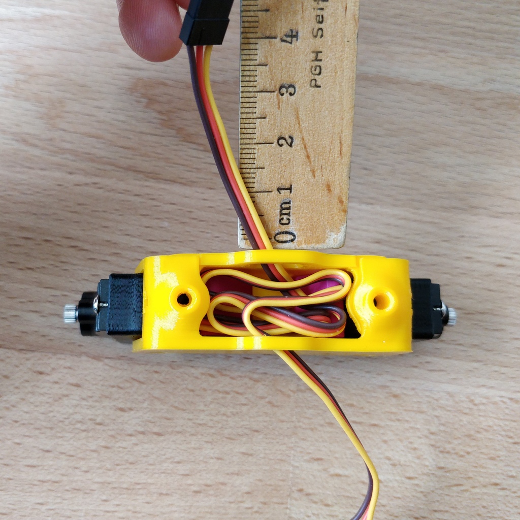
Hold the frame so that one motor is pointing to the left, the other is pointing to the right, and the cables stick out upwards. Now thread the motor cable on the left side of you through the rear hole facing away from you. The right-hand motor cable goes through the hole facing you.
Stow the two motor cables in the frame above the clamp nut so that about 4 cm of cable protrude from the frame.
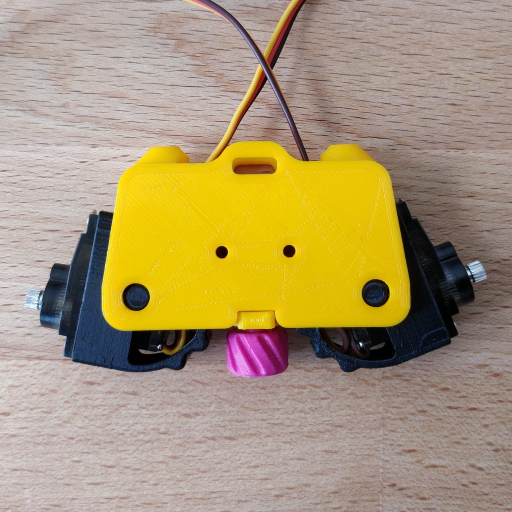
3.3.2. Mounting the circuit board
Now you need the two cylinder head screws (M3x10mm) and the hexagon socket screwdriver. One after the other, insert the screws into the holes in the Bakiwi board and screw them onto the frame.
|
Tip
|
With a bit of luck, the screws can be attached to the hexagon socket screwdriver and are held there by friction; some tools are also magnetic. This usually makes it easier to insert the screws into the holes in the board. |
|
Note
|
Attention, when screwing in for the first time, the screws cut their own thread into the holes in the frame base plate. If you want to loosen and reinsert the screws later, try to feel the thread by turning the screw slightly to the left before tightening it until it fits into the original thread. |
The frame will now hold together by itself, carefully tighten the locking screw a little further with your fingers and test how the motor holders can now be locked in into certain positions.
3.4. Connect the Motor Cables
Now the motors are wired. We already had this step during testing, make sure again that the brown (or black) wires of the motor cables point to the ground symbol (see section Connecting Motors). Stow the two motor cables as far as possible in the frame so that they fit snugly and do not form large loops.
3.5. Attach battery holder
3.5.1. Preparation
Now prepare to attach the battery holders. You need the four M3x4mm cylinder head screws, the hexagon socket screwdriver and the side cutter.
First remove the two spacer bars in both battery compartments by separating them just above the surface. Now screw the battery compartments to the side of the frame. There is now enough space for the screw heads.
3.5.2. Mounting
The battery compartments should be positioned so that the cables are on the side with the sensors. Each holder is fixed to the frame with two screws. Here, too, the screws cut their threads into the holes in the frame the first time they are inserted.
|
Caution
|
Warning! Be careful not to overtighten the screws. |
3.5.3. Stow the battery Cables
Lay the battery cables behind the motor cables along the circuit board to the rear and plug them into their sockets. If necessary, carefully slide the cable under the circuit board.
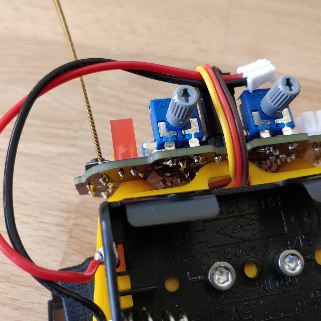
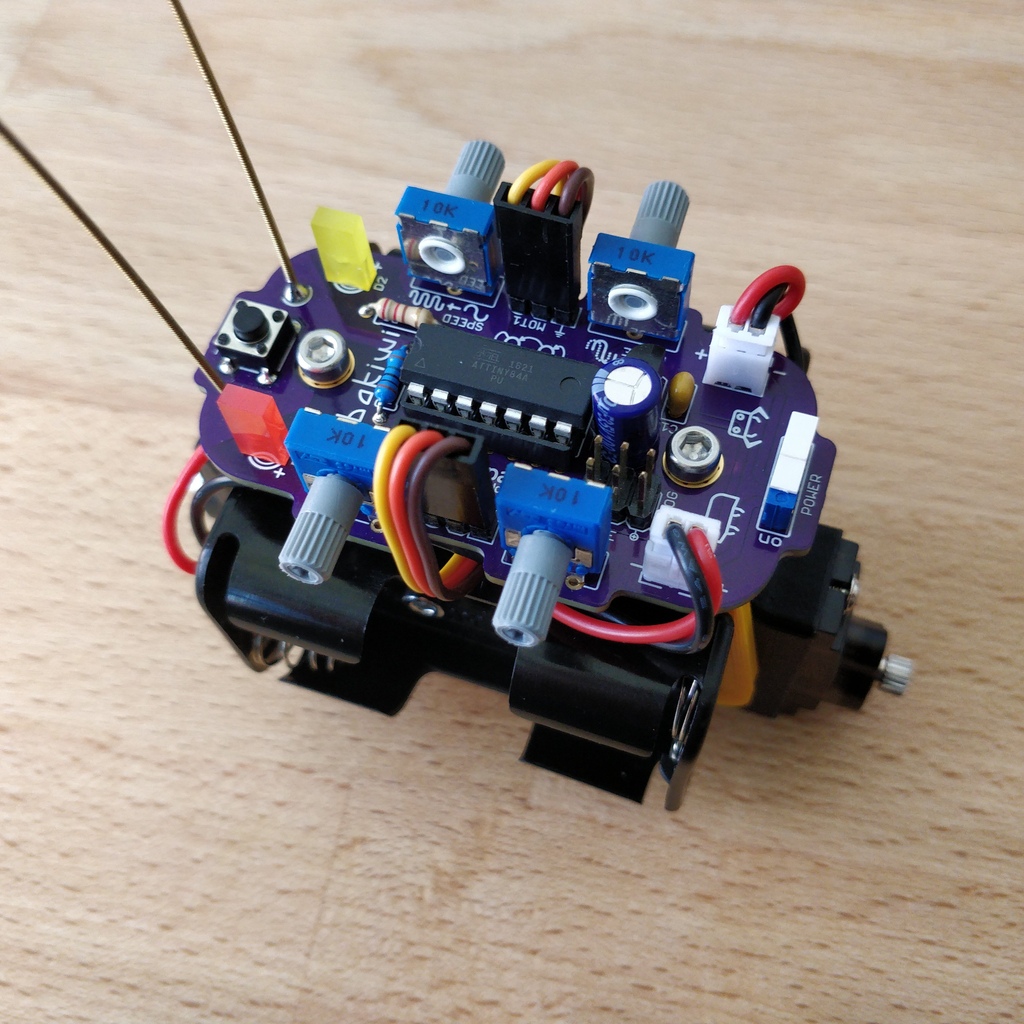
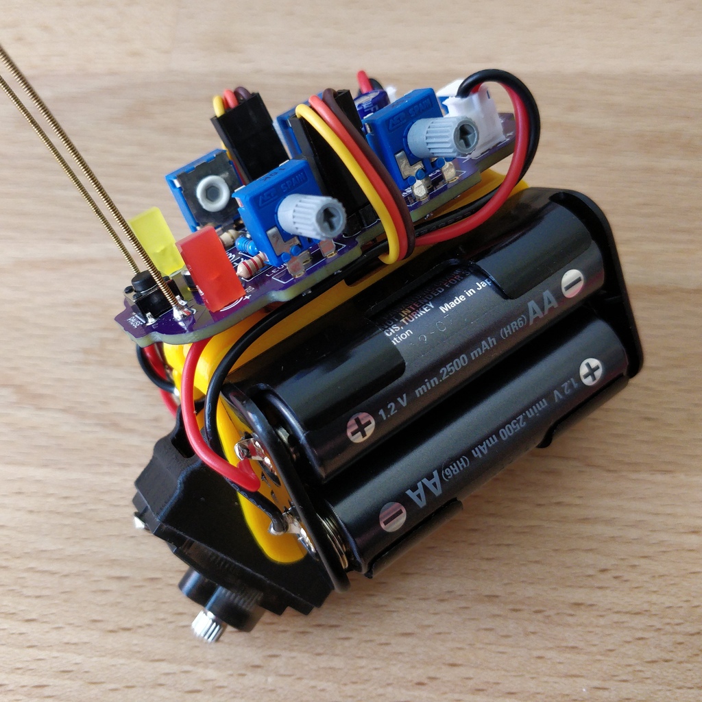
Hooray! Your Bakiwi’s body is finished now. Double check the alignment of the connectors on your circuit board and whether all cables are as close as possible to your Bakiwi’s body.
3.6. Attach Legs
First put the batteries back in and switch on your Bakiwi. Press the PAUSE button twice in succession with an interval of about one second so that your Bakiwi moves its motors to the starting position and then goes back to pause mode.
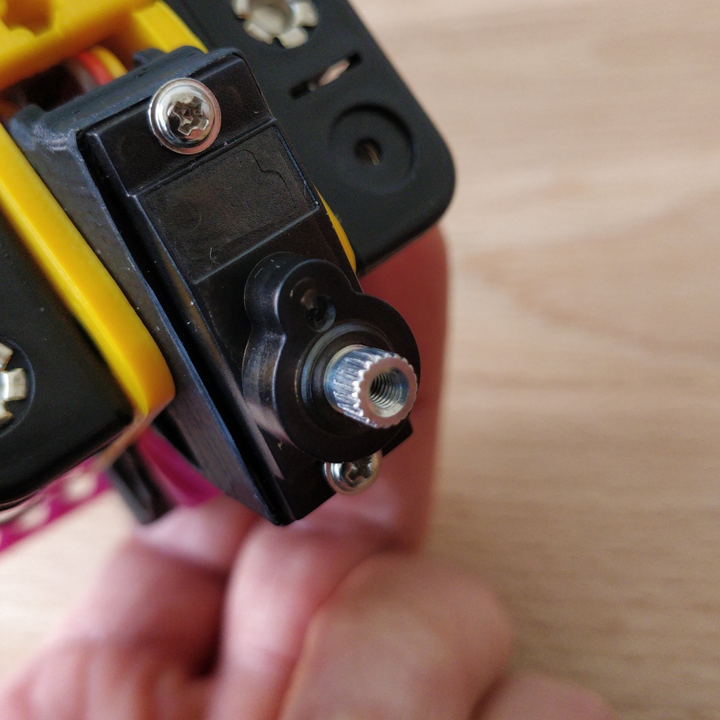
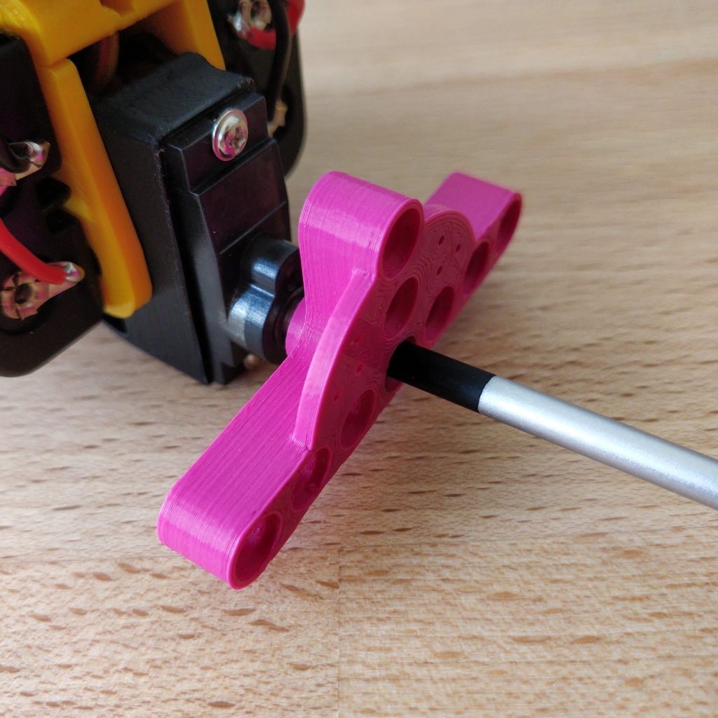
Now mount the leg connections onto the toothed ends of the motors' shafts and screw them tight with the enclosed Phillips screws. It’s the last two screws that are left.
The enclosed 3D-printed leg connections are just one of countless ways to put legs on your Bakiwi. In your kit there are perhaps other parts that fit on the shafts of the motors (so-called horns).
Give yourself a try! With the remaining horns you can make different pairs of legs from different craft materials and switch over and over again.
Done! Depending on which Bakiwi kit you have, there may be small Lego parts included, which can be used as feet for your inital Bakiwi. Maybe you already have Lego Technic parts. You can use these to design legs and feet for your bakiwi very quickly.
4. How to play your bakiwi and how it works
4.1. Before Switching on
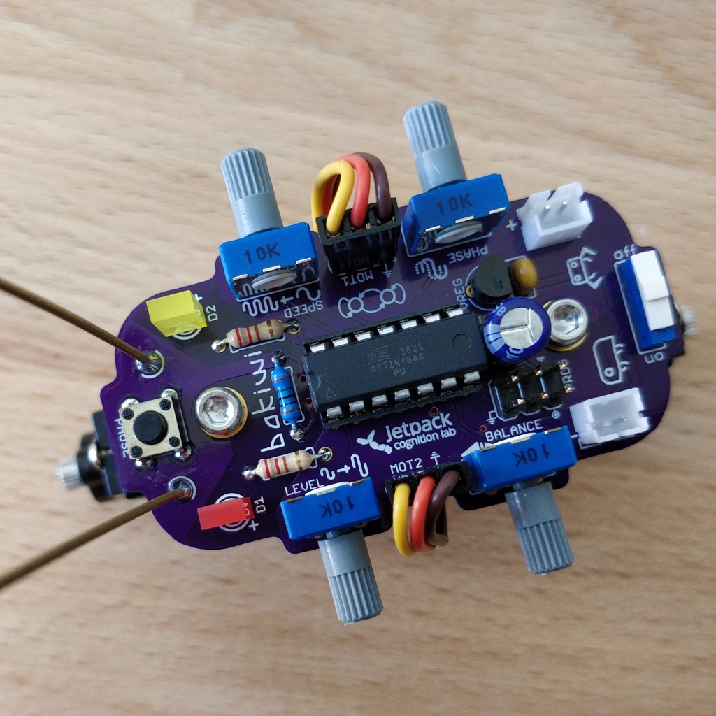
Important: Before switching on for the first time (with the legs attached) take a closer look at the names of the four gray knobs (potentiometers).
-
Set the
BALANCEandPHASEcontrols to the middle position (arrow upwards). -
Set the
SPEEDcontrol halfway to the left (toward the long waveform). -
Set the LEVEL control halfway to the left (toward the small waveform).
Now turn on your Bakiwi.
4.2. The Functionality Explained

In the program memory of your Bakiwi microcontroller there are two neurons that form an oscillator which create the clock signal for the movement of the legs. The two LEDs on your Bakiwi signal the activity of these motor neurons. In the pause mode, the neurons and thus the oscillator are already active and swing, but the motors are inhibited. This means that you can change the movement pattern at any time by adjusting the four knobs, whether paused or not.
We recorded a video to better illustrate how it works:
4.3. Gait Parameters
The way your Bakiwi walks is influenced by several factors. The legs that you create for your Bakiwi are decisive for successful locomotion. If you have come up with new legs for your Bakiwi, you can teach it to walk with them by changing the following parameters:
4.3.1. Motor Joint Angle
The motor joint angles are purely mechanical parameters. You can make the motor mounts movable by loosening the large locking screw and then changing their angles to the body and to each other. Try different angles and watch the difference it makes! Tighten the screw again only until the motor mounts hold firmly enough in the desired position.
4.3.2. Speed/Walking Frequency

The frequency regulates the walking speed of your Bakiwi. Turn the SPEED knob and watch the LEDs change their rate of blinking. Leave the pause mode by pressing the button and observe the motors. Turn the knob back and forth and see how the motor neurons' oscillation speed changes the gait frequency and influences your Bakiwi’s walking speed.
|
Tip
|
We recommend starting with a slow movement first. It helps you to be able to observe the movement of your self-made legs and thus to get a good understanding of the locomotion. |
4.3.3. Level/Amplitude

Turn the LEVEL knob and watch how the brightness of the LEDs changes and how far the motors deflect with every movement. In terms of oscillations this is called the amplitude and controls the step size of your Bakiwi’s gait.
4.3.4. Balance

Turn the BALANCE control and watch how the previously set amplitude is distributed between the two motors. If the controller is in the middle position, both motor amplitudes are the same. Turning to the left decreases the amplitude of the front motor, turning to the right dampens the movement of the rear motor.
4.3.5. Phase

The last parameter, the so-called phase (or the phase angle) is truly the special flavor and controls the direction of movement.
A PHASE controller in the middle position produces a synchronous but opposite movement of the motors. If you turn the phase angle a little out of the middle, the motors no longer move synchronously, which is crucial for walking. A phase angle set up to the maximum (or minimum) again generates a synchronous but this time concurrent movement. The phase is the most important parameter for a successful walking movement and needs your special attention. The phase setting will decide whether your Bakiwi will move at all and if so in which direction.
But read enough now …
Get to work! :)
4.4. Centering
When you have assembled your Bakiwi, you should center its legs if necessary. The motors with the attached leg connections are never perfectly straight due to the manufacturing process. Your Bakiwi can correct this offset and remember it.
To do this, first turn off your Bakiwi.
-
Hold down the pause button and switch on your Bakiwi while holding the button. Both LEDs should now flicker quickly.
-
Release the button and now only the left LED should flicker and the front motor should start up briefly. If you now turn the
PHASEknob you can set the front motor to the desired zero position. Adjust until the leg connection is straight enough. -
Press the button again to confirm. While the right LED is now flickering, you can repeat the process for the rear motor.
-
If the rear motor is also correctly adjusted, confirm again by pressing the button and the centering process is now complete.
|
Tip
|
If you are building new legs for your Bakiwi and the legs, whether intentional or unintentional, are not symmetrical you can also use the centering method to compensate for any offset. But you can also use it specifically to let your Bakiwi always run a curve. |
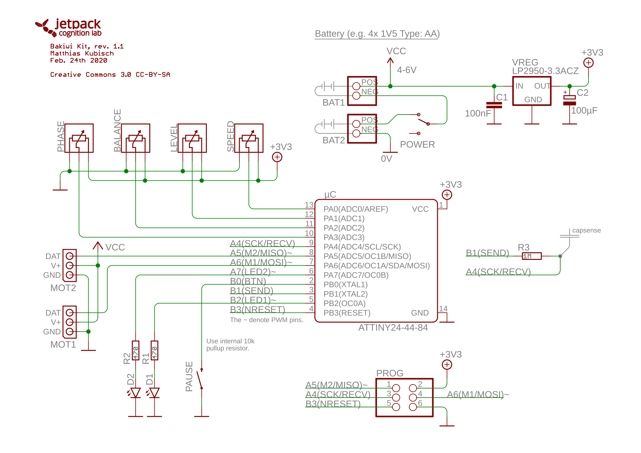
4.5. Schematics
Below you can see the circuit diagram (schematics) of your Bakiwi. Can you find out for yourself which symbols belong to which parts you soldered? Reading a circuit diagram takes some practice, but now that you have soldered all the parts together yourself, you can see here which component is wired to which. The cables on a circuit board are called tracks and consist of a thin layer of copper. If you look at the circuit board of your Bakiwi and hold it slightly up to the light, you can see them under the layer of varnish. Some tracks change the side of the board through small holes, so-called vias. Some tracks are also whole areas, for example the entire bottom copper area of the board is the negative pole.
A circuit diagram also helps with troubleshooting. If the electronics behave strangely, a multimeter and a circuit diagram are the most important tools in finding the cause. The components are also precisely identified in the circuit diagram. There you will find, for example, the resistors' values, the capacitance of the capacitors, the forward direction of the diodes or what the name of the voltage regulator is. With the help of a circuit diagram, an electrical device, like your Bakiwi, can be repaired over and over again.
Do you have any questions?
Do you have any questions or would you like further explanations? Do you have any suggestions or feedback for us? Write us!
You can also follow us on Twitter, there we will provide you with news about #bakiwi. We are @LabJetpack.
Otherwise we wish you a lot of fun with your new Bakiwi. Let it crawl!